How to Select Waterproof Cable Harnesses for Marine Environments?
Lightning strikes pose a critical threat to the stable operation of traffic signal systems. The immense energy generated can readily invade through power and signal wire harnesses, causing equipment damage and traffic paralysis. For lightning protection design of wire harnesses, a <strong>three-pronged integrated protection system</strong> encompassing <strong>external direct-strike protection, induced lightning surge suppression, low-resistance grounding, and precision construction</strong> must be established. This forms a solid foundation for ensuring the safe and reliable operation of urban traffic signals.
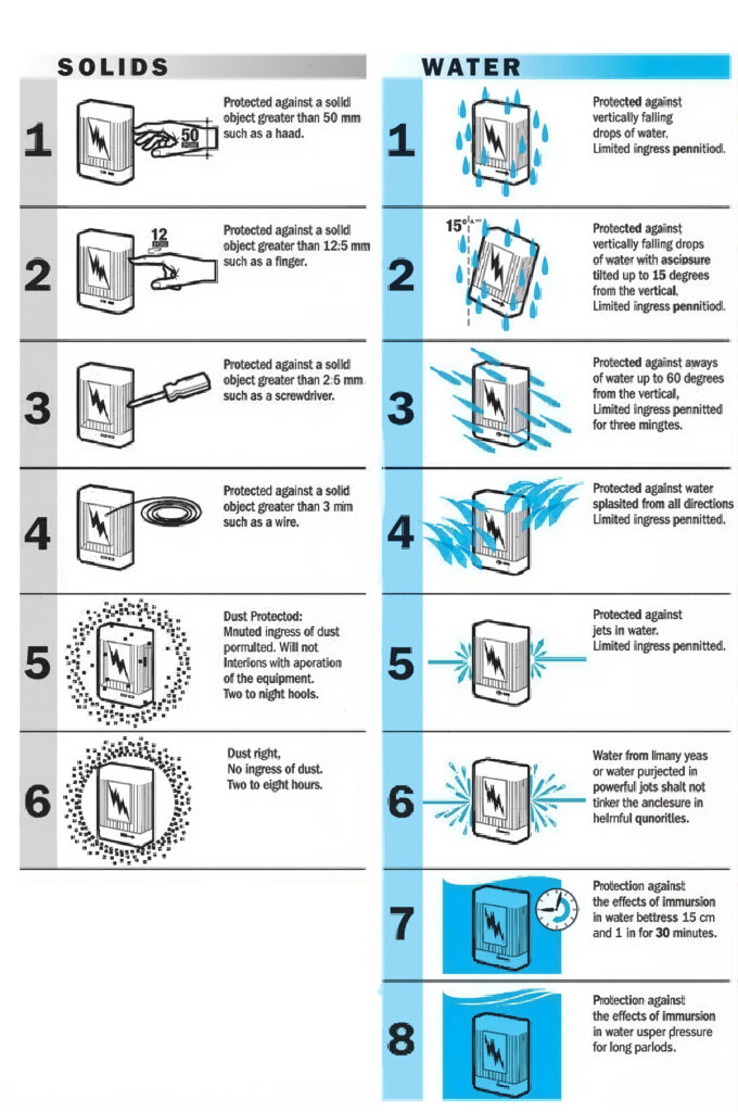
1. Harness waterproof Rating (IP Protection Standard)
In marine environments, water vapor penetration and direct immersion are primary causes of harness failure.
The International Protection (IP) code is the core standard for evaluating waterproof performance.
1.1 Differences and Applications of IP67 vs IP68 vs IP69K
- IP67: Withstands temporary immersion (1m depth for 30 minutes), suitable for decks and bulkheads with splash exposure but not prolonged submersion.
- IP68: Supports continuous underwater operation (depth/duration specified by manufacturer), ideal for underwater sensors and propulsion systems.
- IP69K: Resists high-pressure/high-temperature water jets, perfect for deck equipment requiring regular cleaning.
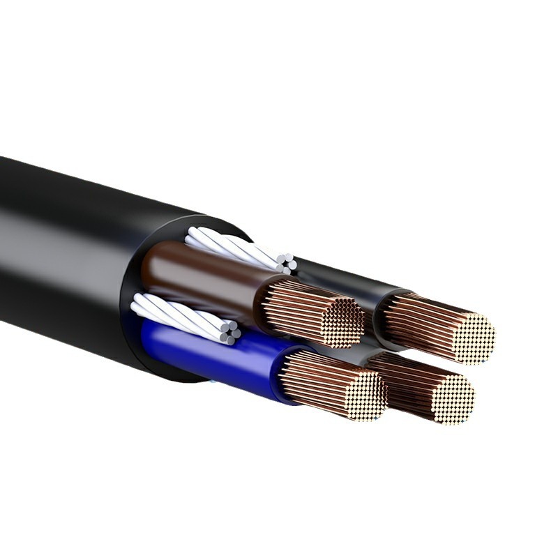
1.2 Waterproof Structure Design
- Multi-layer sealing: Premium harnesses use triple protection with rubber gaskets, heat-shrink tubing, and potting compound.
- Connector waterproofing: e.g., SUBMARINE series connectors achieve IP68 via threaded locking and silicone sealing.
Testing recommendation: Measure insulation resistance >100MΩ after 24-hour immersion test.
2. Salt Spray Corrosion Resistance
Salt spray corrodes metal conductors and connectors, increasing resistance or causing open circuits. Statistics show 80% of marine electrical failures relate to salt corrosion.
2.1 Material Selection
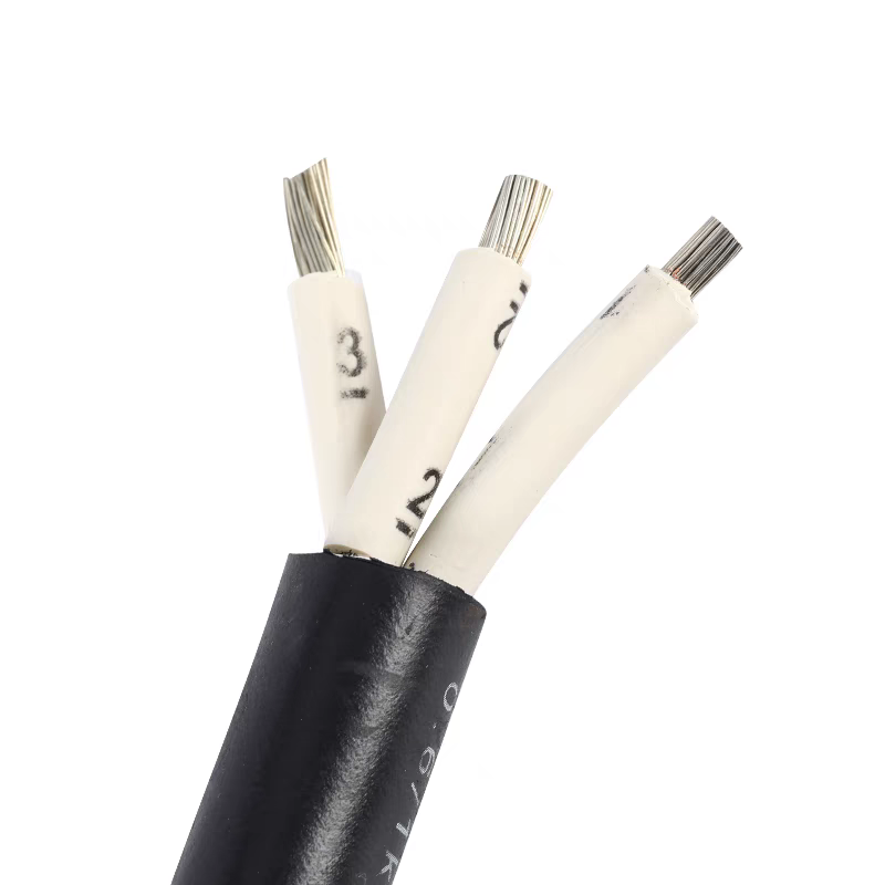
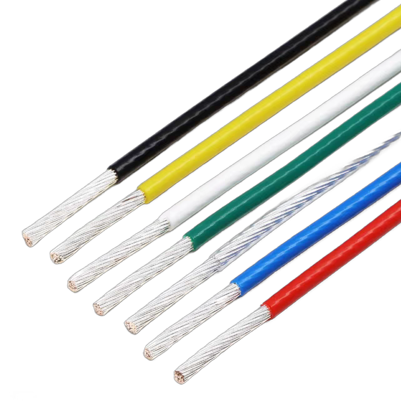
Conductor:
- Tin-plated copper :3× better oxidation resistance than bare copper
- Silver-plated copper : For high-frequency signal transmission scenarios
Insulation:
- Polyurethane (PUR) : Hydrolysis-resistant, ideal for dynamic bending areas
- Cross-linked polyethylene (XLPE): Withstands 90°C, more cost-effective
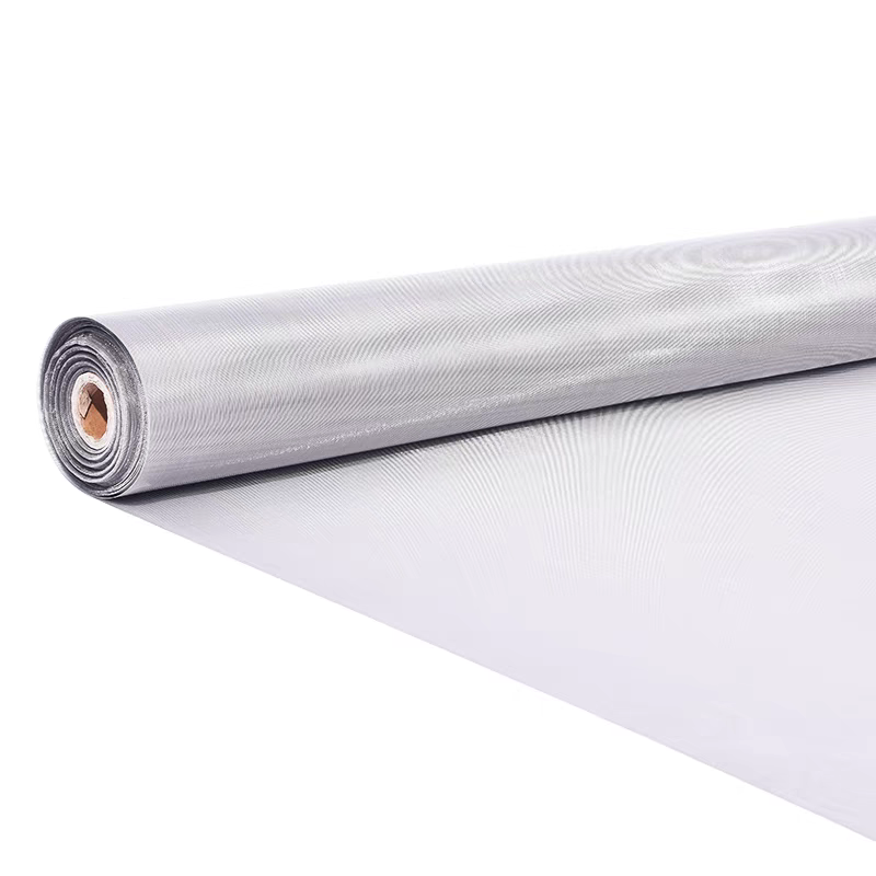
2.2 Protection Techniques
- Nickel-plated shielding: Extends salt spray lifespan by 50% via nickel plating on copper braid
- Armored protection: Stainless steel braiding provides dual mechanical+chemical protection
2.3 Salt Spray Testing Standards
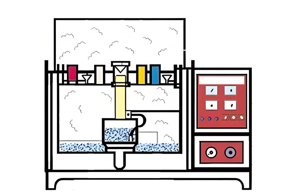
- ISO 9227: After 500hr neutral salt spray test, conductor resistance change <10%
- ASTM B117: US military standard with stricter requirements
3. Vibration and Mechanical Resistance
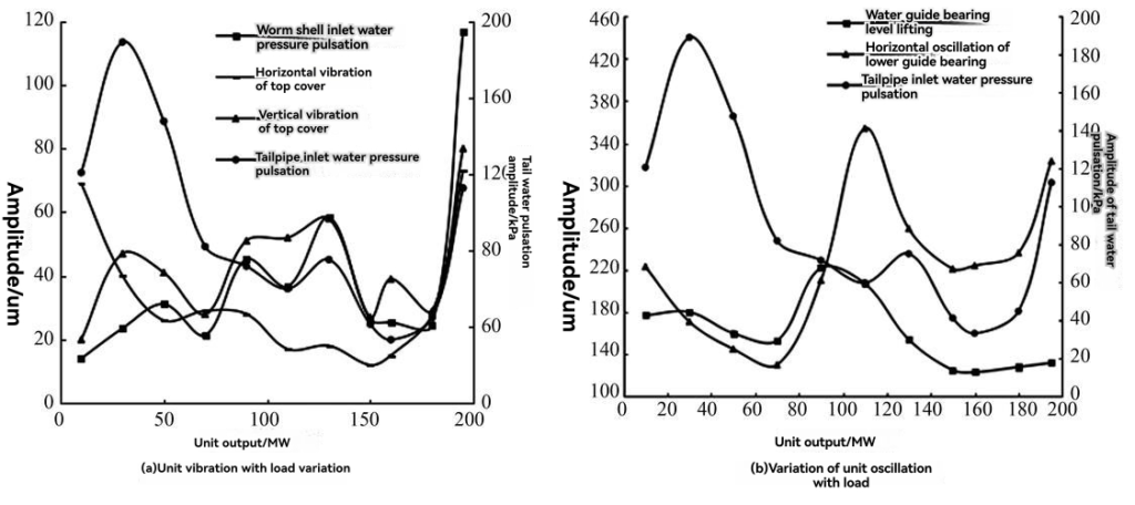
Ship vibrations mainly come from three sources:
main engine vibration (low frequency, large amplitude), wave impact (random vibration), and equipment operation (high-frequency vibration).
3.1 Anti-vibration Design Details:
- The pitch of spiral sleeves should be ≤15mm for effective vibration damping
- Aramid fiber has 5 times the tensile strength of steel wire but is more expensive
- Critical areas should use dual protection: steel wire armor + rubber vibration damping
3.2 Installation and fixing standards:
- Cable clamp spacing should not exceed 30cm , with increased density at bends
- Vibration-prone areas must use anti-loosening metal clips
- Install vibration-damInstall vibration-damping sleeves when passing through bulkheads.
4. Chemical Corrosion Resistance
4.1 Chemical corrosion risks vary by area:
Fuel tank areas:
- Fluororubber (FKM) harnesses are recommended, offering 10 times better fuel resistance than standard rubber.
- Note : Select low-permeability models
Cleaning agent effects:
- Common marine cleaners have a pH range of 2-12 . PTFE is the only fully resistant material , but CPE rubber can be used for cost efficiency
Environmental requirements:
- RoHS compliance for six restricted hazardous substances is mandatory
- REACH regulates 38 substances—request up-to-date compliance certificates
5. Temperature Adaptability
5.1 Key points for temperature adaptation:
Material temperature ranges:
- Silicone rubber performs best in low temperatures but has poor mechanical strength.
- PTFE offers the highest heat resistance (260°C).
- Standard EPDM rubber suits -50°C to 150°C.
Extreme environment strategies:
- For Arctic routes , test harness flexibility at -60°C .
- In high-temperature engine rooms , derate materials (e.g., use 100°C for 125°C-rated ones)
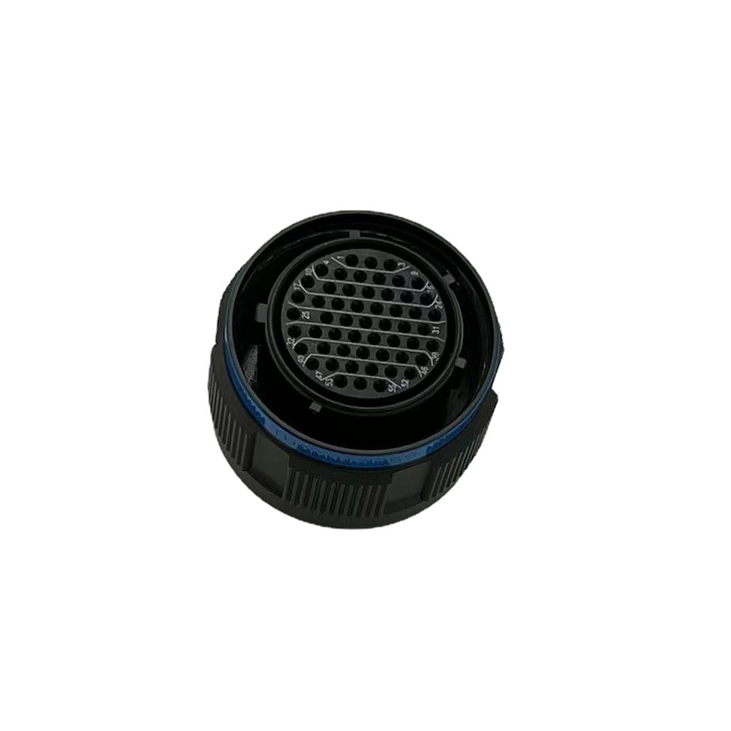
6. Connector Waterproof Design
6.1 Connector selection guidelines:
Military-standard connectors:
- MIL-DTL-5015 series suits high-current applications but is bulky
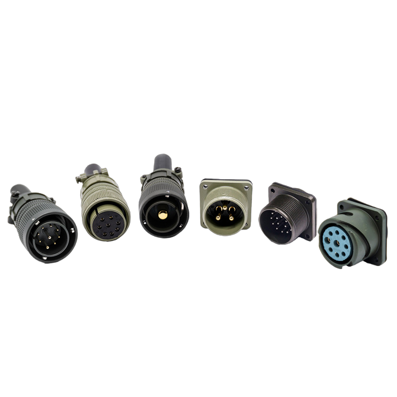
- MIL-DTL-38999 series is more compact for signal transmission.
Potting material options:
- Epoxy resin is rigid but hard to repair
- Silicone offers elasticity for easier maintenance.
- Polyurethane strikes a balance.
Contact treatment:
- Gold plating (≥0.5μm) is optimal.
- Silver plating requires anti-sulfuration measures.
7. Industry Certifications and Standards
7.1 Key certification insights:
IEC 60092-350:
- The latest version mandates halogen-free materials and stricter smoke density criteria.
Classification society certifications:
- DNV GL, ABS , and LR typically require 3–6 months for certification—plan ahead
Special zone requirements:
- Hazardous areas need IEC 60092-502 explosion-proof compliance
- Passenger ships require IMO FTP Code fire tests
8. Typical Application Solutions
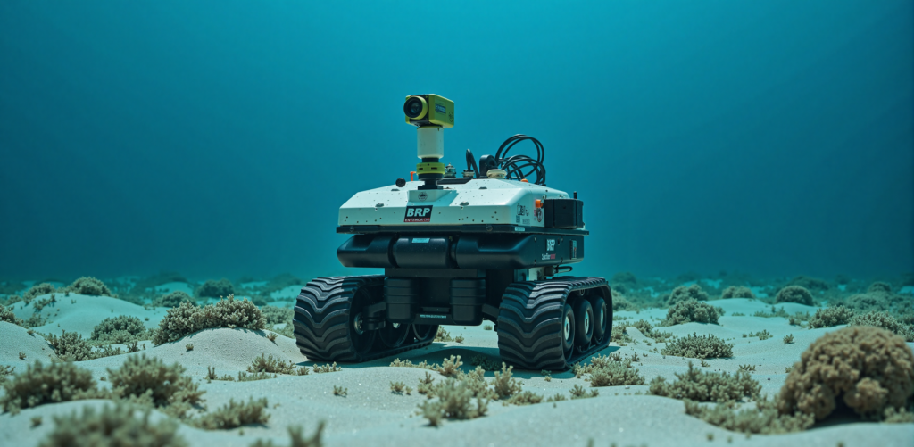
Underwater robot harnesses:
- IP68 + gold-plated connectors + PTFE insulation + stainless steel braiding. Cost : 10× standard harnesses
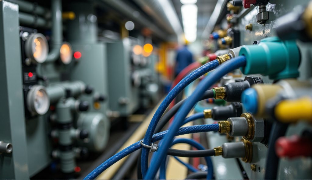
Engine room harnesses:
- Must resist oil , high heat, and vibration. Typical: FKM jacket + XLPE insulation + aramid reinforcement .
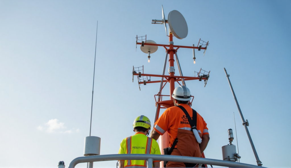
Radar mast harnesses:
- Lightning protection is critical; shield grounding resistance <0.1Ω (<0.1Ω).
▼▼Selection Process Details▼▼
1. Define Environmental Parameters
Before selection, thoroughly assess the operating environment. Create a detailed parameter checklist:
⑴ Hydrological parameters:
- Max. operating depth (determines IP rating)
- Wave splash frequency (short-term waterproof needs)
- Flexing frequency (movable joint cycles)
⑵ Mechanical environment:
- Vibration spectrum (main/auxiliary engine frequencies )
- Shock intensity (e.g., naval gunfire impulse)
- Flexing frequency (movable joint cycles)
⑶ Chemical environment:
- Oil types contacted (fuel/lubricant/hydraulic)
- Cleaner types and usage frequency.
- Special corrosives (e.g., hydrogen sulfide )
⑷ Temperature parameters:
- Extreme heat (e.g., engine room hotspots )
- Extreme cold (Arctic operations )
- Thermal cycling rate
2. Identify Required Certifications
Certification requirements vary by vessel type and operating region:
⑴ Vessel type differences:
- Commercial ships : Focus on IEC standards
- Military vessels: MIL standards
- Special vessels : LNG carriers need explosion-proof certs
⑵ Navigation zone requirements:
- Arctic routes: Add -60°C low-temp tests
- Tropical waters : Enhanced mold resistance
- Hazardous areas: ATEX/IECEx certification
⑶ Classification society variations:
- DNV GL: Strictest environmental rules
- ABS: Emphasizes mechanical performance
- CCS: Mandatory for China-flagged ships
3. Select Materials and Structures
Design material combinations based on steps 1–2 data:
⑴ Conductor selection matrix:
| Scenario | Recommended Conductor | Plating Requirement |
| General power | Tin-plated copper | 3μm |
| High-frequency signals | Silver-plated copper | 2μm |
| Extreme corrosion | Nickel-plated copper | 5μm |
⑵ Insulation structure options:
- Tri-layer co-extrusion: Inner shield + insulation + outer shield
- Armoring choices : Stainless steel wire/aramid fiber
- Special protection : Capsaicin additives for rodent resistance
⑶ Cost optimization tips:
- Use XLPE instead of PTFE in non-critical areas
- Reduce armor in low-vibration zones
- Downgrade to IP66 for non-immersed areas
4. Sample Environmental Testing
Establish a complete test protocol:
⑴ Combined test sequence:
- 500h salt spray → 50 thermal cycles → 100h vibration → Final waterproof verification
⑵ Key test metrics:
- InsulInsulation resistance : >100MΩ (500VDC)
- Withstand voltage : 2.5× rated voltage no breakdown
- Mechanical performance : <5% resistance change after 5,000 bends
⑶ Accelerated aging tests:
- 1,000h at 85°C/85%RH = 5 years real-world use
5. Small-Batch Trial Evaluation
Develop phased validation plans:
⑴ Trial design:
- Initial quantity : 1–2% of total demand
- Duration: ≥3 months
- Locations: Most representative operating point
⑵ Monitoring methods:
- Online: Temperature/insulation sensors
- Periodic checks : Monthly conductor resistance measurements
- Post-trial dissection : Internal inspection
⑶ Evaluation criteria:
- Failure rate : <0.1%/1,000 hours
- Performance degradation : <5%
- Maintenance hours : <50% of standard harnesses