How to Determine if Wiring Harness Needs Replacement?
Lightning strikes pose a critical threat to the stable operation of traffic signal systems. The immense energy generated can readily invade through power and signal wire harnesses, causing equipment damage and traffic paralysis. For lightning protection design of wire harnesses, a <strong>three-pronged integrated protection system</strong> encompassing <strong>external direct-strike protection, induced lightning surge suppression, low-resistance grounding, and precision construction</strong> must be established. This forms a solid foundation for ensuring the safe and reliable operation of urban traffic signals.
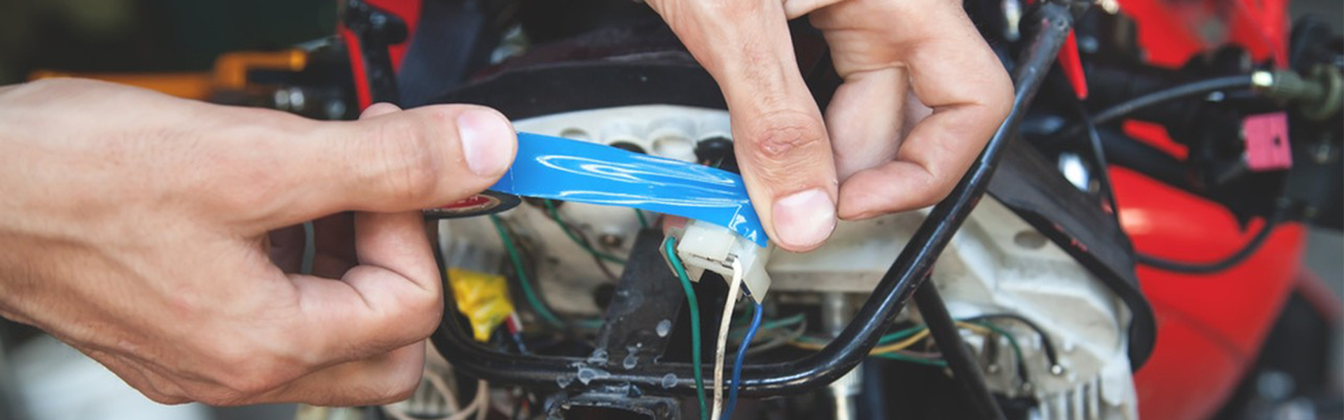
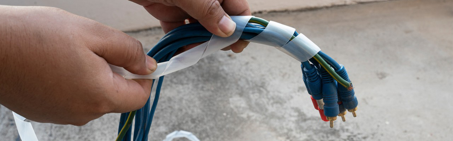
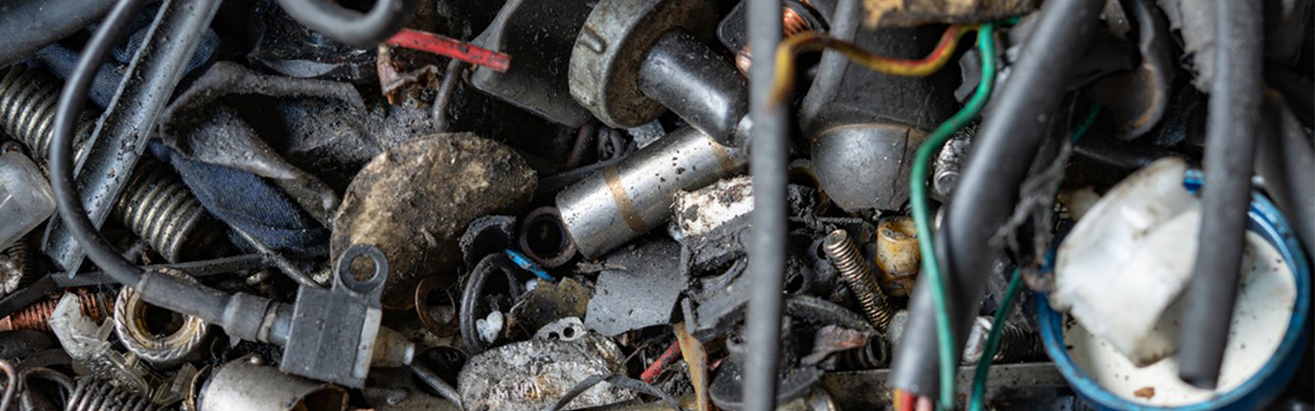
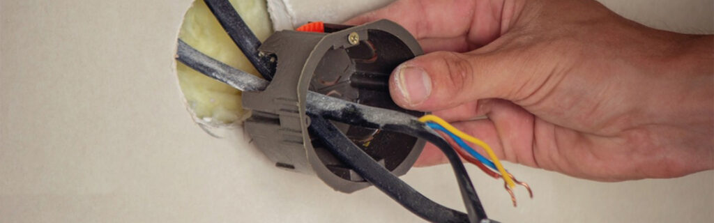
1. Visual Inspection
Visual inspection is the most direct and quickest assessment method, as most issues can be identified through observation and touch. Here are the key aspects to focus on:
1.1 Insulation Damage
▶ Cracks or cuts: Check for visible physical damage on the harness surface, such as cuts from sharp objects, crushing deformation, or wear caused by long-term friction.
▶ Signs of aging: Hardening, brittleness, discoloration, or powdery residue on the insulation layer indicate material degradation, which may compromise protection.
▶ Swelling or bubbling: Localized bulging or bubbling of the insulation suggests internal short-circuiting and overheating, causing the insulation to melt.
1.2 Exposed Conductors
▶ Exposed copper wires: Damaged insulation exposing internal metal conductors can easily cause short circuits, leakage, or grounding faults.
▶ Harness deformation: Flattened, twisted, or stretched harnesses may have broken internal wires, affecting conductivity.
1.3 Connector Damage
▶ Burning or oxidation: Blackened, rusted, or greenish (copper oxide) plugs/sockets can lead to poor contact or increased resistance.
▶ Pin deformation: Bent, broken, or loose pins may cause intermittent power loss or signal transmission issues.
▶ Seal deterioration: Cracked or hardened gaskets on waterproof harnesses may allow moisture ingress, leading to corrosion or short circuits.
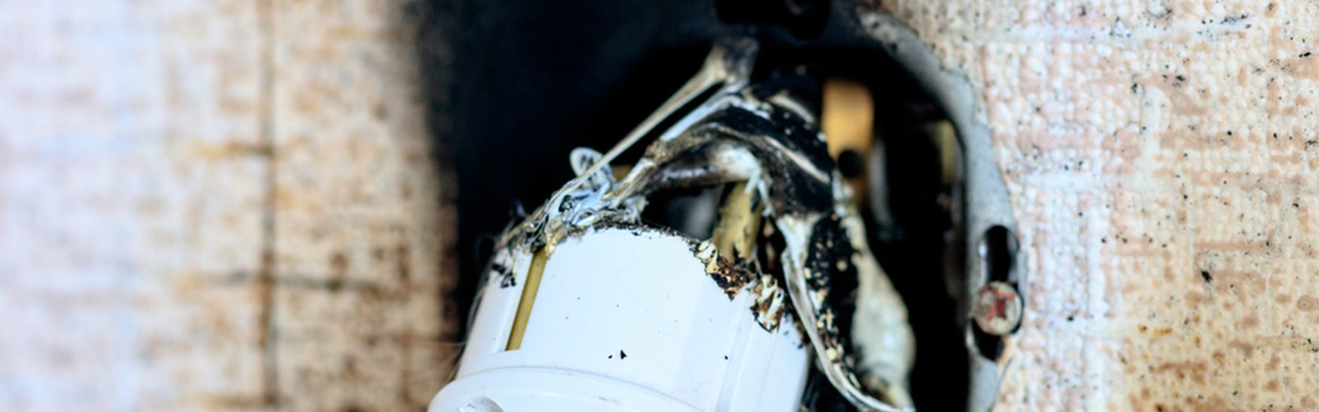
1.4 Connector Damage
▶ Burn marks: Charred or blackened areas near the harness or connectors indicate past overloading or short circuits, requiring immediate replacement.
▶ Oil or chemical stains: Contact with engine oil, brake fluid, or battery acid may corrode insulation, cause swelling, or reduce conductivity.
▶ Animal damage: Teeth marks or chewed sections require immediate replacement and protective measures (e.g., rodent-proof sleeves).

1.5 Loose or Missing Fasteners
▶ Broken cable ties: Loose harnesses may rub against moving parts or wear prematurely.
▶ Missing clips: Factory harnesses often use clips; their absence may cause excessive movement and friction damage.
Summary
Visual inspection quickly reveals common harness issues. If you find damaged insulation, exposed conductors, connector faults, or burn marks, replace the harness promptly to prevent severe electrical failures. For uncertain cases, proceed with functional tests or professional diagnostics.
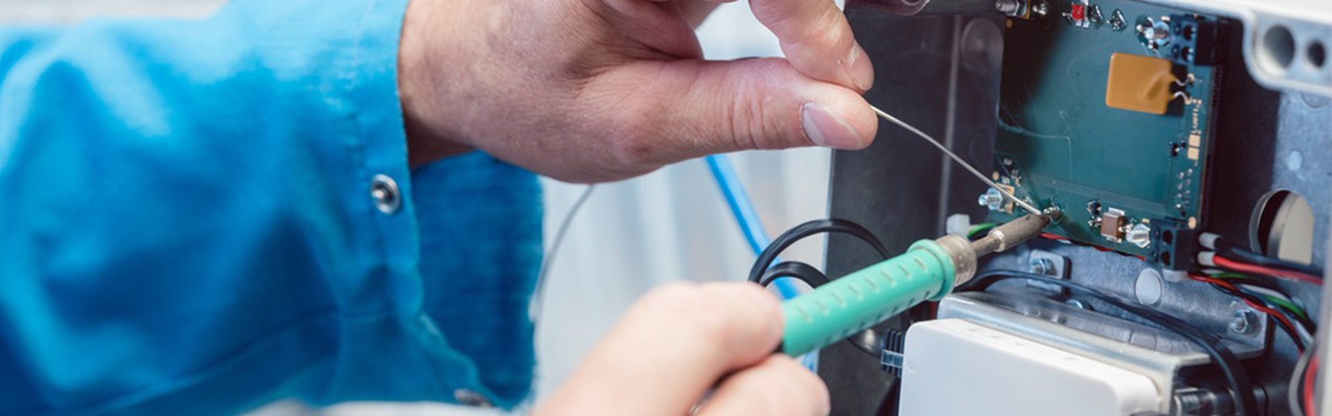
2. Functional Abnormalities
2.1 Electrical Faults
▶ Intermittent power failure or device malfunction
▪ Equipment (e.g., lights, motors, sensors) working intermittently may indicate poor harness contact or internal wire breakage.
▪ Gently wiggle the harness while observing equipment response to locate faults.
▶ Frequent fuse blowouts
▪ Repeated fuse failures in the same circuit suggest short circuits (positive/negative contact) or overload (insufficient wire gauge).
▪ Inspect for burnt marks, insulation damage, or abnormal grounding.
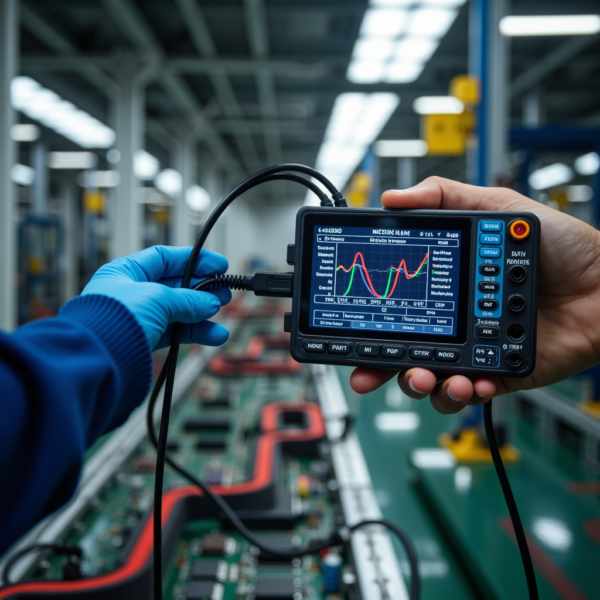
▶ Signal transmission issues (for communication harnesses)
▪ CAN bus or sensor signal lines showing packet loss, errors, or disconnection.
▪ Use an oscilloscope to check waveform integrity or measure terminal resistance.
2.2 Abnormal Heating
▶ Localized overheating
▪ If certain harness sections feel noticeably hot, this may indicate high contact resistance (oxidation/looseness) or overload.
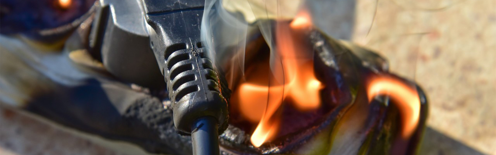
▪ Prolonged overheating accelerates insulation degradation and may cause fires.
▶ Burn marks or odors
▪ Burnt smells, blackened areas, or melted plastic require immediate replacement.
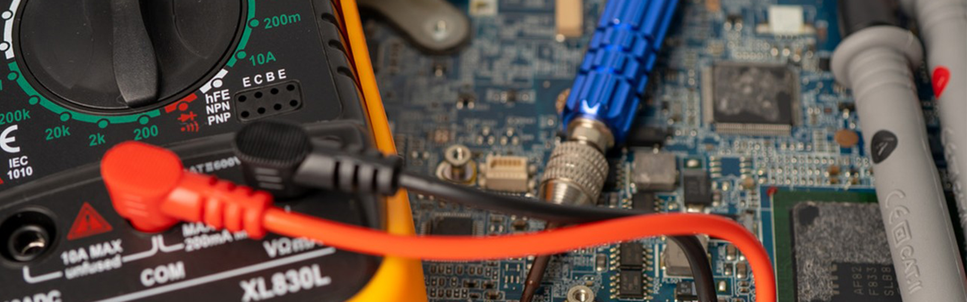
2.3 Voltage/Resistance Anomalies (Requires Multimeter)
▶ Excessive voltage drop
▪ Under load, measure voltage at both ends. A drop exceeding standards (e.g., >0.5V in 12V systems) indicates high resistance or poor contact.
▶ Resistance abnormalities
▪ Open circuit: Infinite resistance (OL) means wire breakage.
▪ Short circuit: Near 0Ω between wire-to-ground or wire-to-wire indicates a short.
▪ Contact resistance: Connectors should measure near 0Ω; >1Ω requires cleaning/replacement.
2.4 Device Malfunction Without Error Codes
▪ Some harness issues may cause performance degradation (e.g., unstable motor speed, dim lights) without triggering fault codes – prioritize power/ground wire checks.
2.5 Load Testing (High-Current Detection)
▪ Test high-power circuits (starter, headlight harnesses) under load to check for voltage drops or overheating, indicating insufficient current capacity.
Summary: When Replacement is Mandatory
▶ Replace harnesses if:
✅ Recurring unfixable shorts/opens.
✅ Critical circuits (power/signal) show abnormal resistance/voltage affecting operation.
✅ Safety hazards like overheating or burns exist.
These methods ensure accurate diagnosis to prevent costly failures.
3. Environmental and Historical Factors
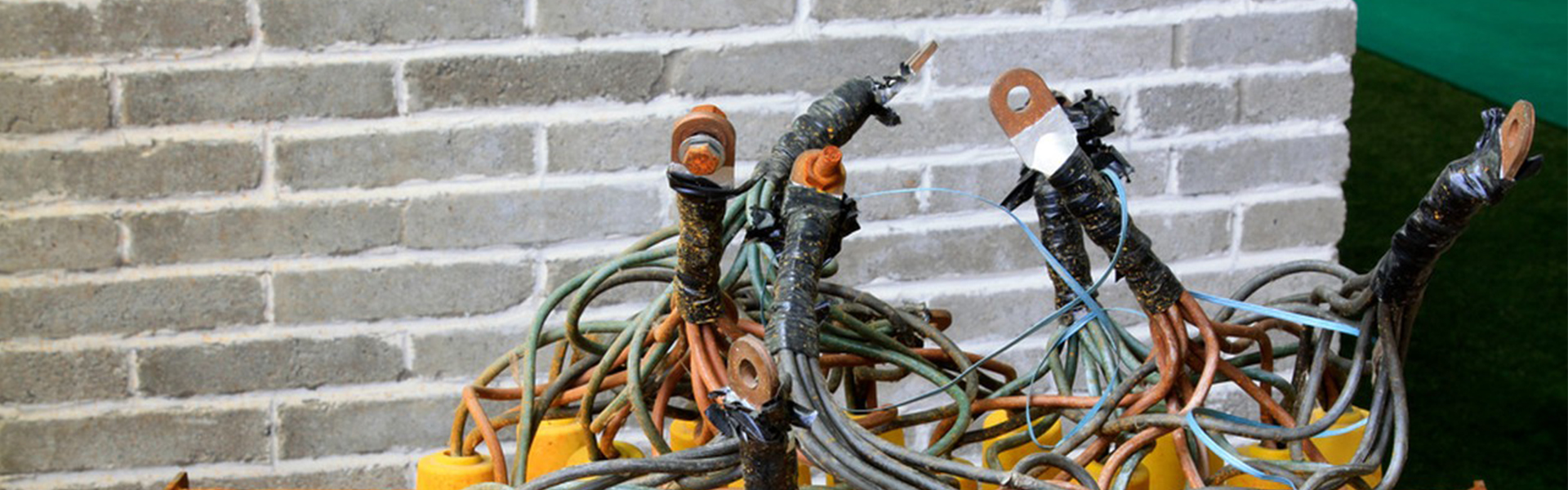
3.1 Corrosion or Contamination
▶ Liquid exposure
▪ Prolonged contact with water, oil, coolant or brake fluid may cause insulation swelling and conductor oxidation.
▪ Water-immersed vehicles (e.g., off-roaders, flood-damaged cars) often develop moisture damage and connector corrosion.
▶ Chemical corrosion
▪ Coastal areas or road salt accelerates metal conductor and connector corrosion.
▪ Contact with strong acids/alkalis (e.g., battery leaks) makes insulation brittle and turns copper wires green.
▶ Dirt/oil buildup
▪ Engine compartment grime can block harness heat dissipation, causing localized overheating.
3.2 Animal Damage
▶ Rodent chewing (mice, squirrels)
▪ Gnawed insulation or severed wires cause open/short circuits.
▪ Common in long-stored vehicles or warehouse equipment.
▶ Insect/spider nests
▪ Webs or secretions in harness gaps may cause moisture damage or shorts.
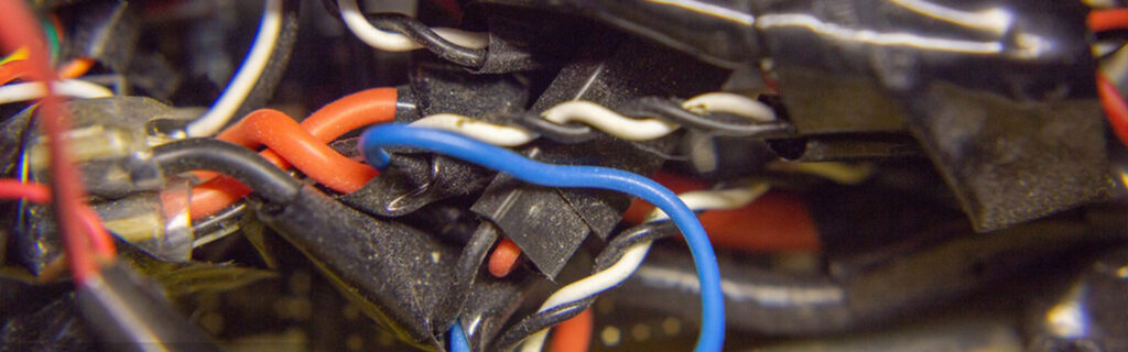
3.3 Modification or Repair History
▶ Unprofessional modifications
▪ Aftermarket high-power devices (audio systems, LEDs) may overload harnesses.
▪ Improper wiring (e.g., “flying wires,” tape repairs) often leads to poor contacts or shorts.
▶ Accident repair impacts
▪ Post-collision harnesses may have internal wire breaks despite intact appearance.
▪ Temporary repairs often fail long-term if damaged harnesses aren’t replaced.

3.4 Extreme Temperature Effects
▶ High-temperature environments
▪ Engine bay or exhaust-adjacent harnesses suffer brittle, aged insulation.
▪ Heat-distorted connector plastics cause intermittent contacts.
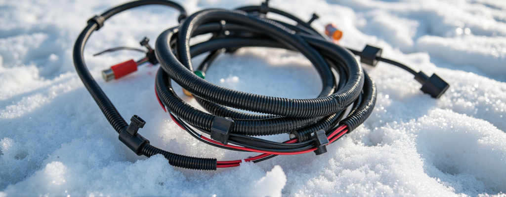
▶ Low-temperature environments
▪ Arctic conditions make harnesses stiff and prone to cracking when bent.
▪ Thermal cycling may form condensation inside connectors, causing rust.
3.5 Vibration and Mechanical Wear
▶ High-vibration areas (engine, chassis harnesses)
▪ Loose clips lead to abrasion against metal parts.
▪ Vibrations gradually loosen connectors, increasing contact resistance.
▶ Frequent bending points (door hinge harnesses)
▪ Repeated flexing breaks internal strands, causing intermittent faults.
Replacement Criteria
▶ Replace harnesses if:
✅ Severely oxidized connectors remain faulty after cleaning.
✅ Multiple wires show sticky/peeling insulation from oil/salt corrosion.
✅ Accidents/modifications deformed harnesses or exceeded load ratings.
✅ Long-term exposure to heat/moisture/vibration with functional issues.
Combining environmental/historical analysis ensures accurate harness assessments and prevents safety risks.
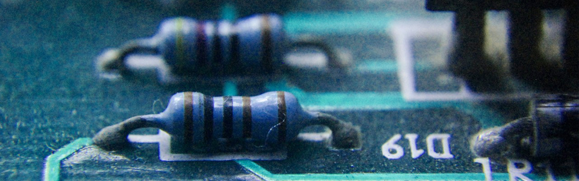
4. Aging Signs
Wire harness aging is one of the main causes of performance degradation and failure. Aging typically results from long-term use, environmental erosion, or material deterioration. Here are key signs indicating whether a harness needs replacement due to aging:
4.1 Service Life
▶ General lifespan: The designed service life of wiring harnesses in vehicles or electrical equipment is typically 8-12 years, but this shortens in high-temperature, humid, or high-load environments.
▶ Overuse risks: Harnesses exceeding their lifespan may develop internal insulation brittleness causing shorts or opens, even if appearing intact.
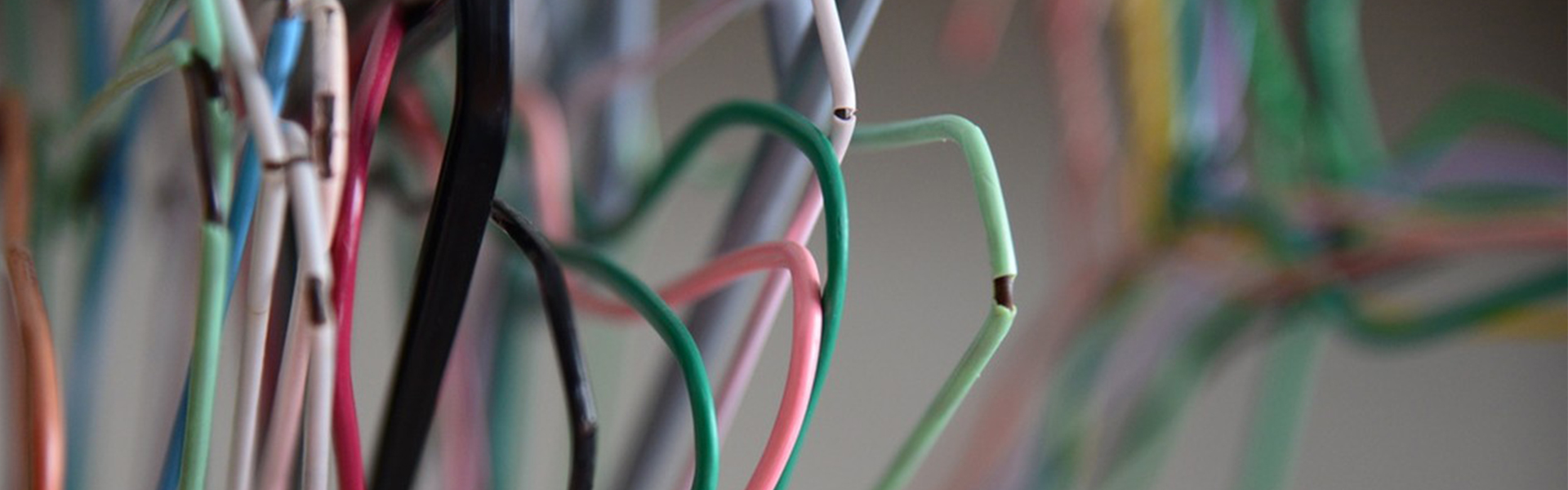
4.2 Insulation Deterioration
▶ Hardening/cracking: Insulation loses flexibility when bent, becoming prone to cracking or peeling.
▶ Surface powdering: White powder (plasticizer leaching) indicates severe material aging.
▶ Discoloration: Black insulation turning gray/yellow (UV or heat-induced oxidation).
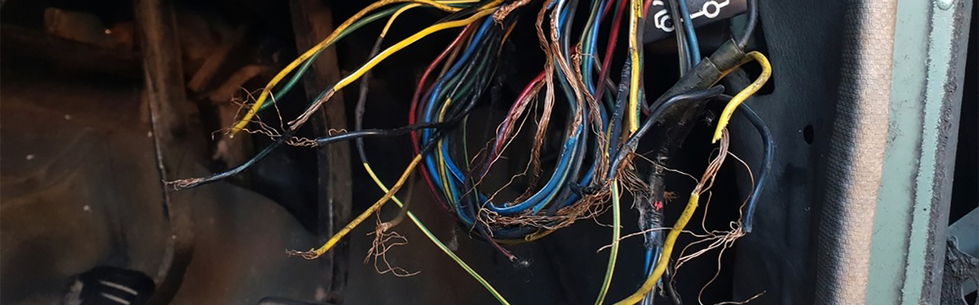
4.3 Conductor Oxidation/Corrosion
▶ Black/green copper wires: Exposed copper strands showing oxidation (blackening) or patina (from moisture/chemicals) increase resistance.
▶ Broken strands: Partial fractures in multi-strand wires from repeated bending or corrosion.
4.4 Connector Aging
▶ Brittle plastic housings: Crumbling or cracked connector shells compromise secure contacts.
▶ Oxidized terminals: Blackened or rusted pins (e.g., worn gold plating) raise contact resistance.
4.5 Loss of Elasticity (e.g., Conduits, Ties)
▶ Split protective sleeves: Corrugated tubes or tapes become brittle, failing to shield wires.
▶ Loose cable ties: Broken or slack ties allow harness movement and abrasion.
4.6 Performance Decline History
▶ Increasing faults: Intermittent stalling or flickering lights may signal aged harness contacts.
▶ Repair records: Repeated fixes (splicing, taping) indicate declining reliability.
Replacement Guidelines for Aged Harnesses
▶ Replace proactively if:
✅ Extensive insulation cracks/hardening that fractures upon slight bending.
✅ Severe conductor oxidation with abnormally high resistance (per multimeter tests).
✅ Connector plastic degradation or pin corrosion compromising stable connections.
Note: Aged harnesses may function temporarily but pose hidden risks (fires, sudden failures). Regular inspections and timely replacement are advised.
▼ Professional Testing Methods▼
| Test Method | Purpose | Tools | Procedure | Application Scenarios |
| Continuity Test | Check for open circuits or poor connections | Digital multimeter (Ω mode) | 1. Disconnect both ends 2. Set to resistance mode 3. Measure: – Normal: <1Ω – Open: “OL” 4. Locate faults | – Vehicle electrical systems – Industrial control circuits |
| Insulation Resistance Test | Detect insulation aging/damage/moisture | Megohmmeter (500V/1000V) | 1. Disconnect harness 2. Connect (+) to wire, (-) to ground 3. Test for 1 min: – Pass: >1MΩ – Fail: <0.5MΩ 4. Check causes | – EV high-voltage harnesses – Humid environments |
| Voltage Drop Test | Evaluate conductivity under load | Digital multimeter (V mode) | 1. Power on circuit 2. Measure voltage at both ends – Red: power, Black: load 3. Calculate drop: – Normal: <0.5V(12V)/<2V(48V) – Abnormal: >1V | – High current circuits – Long distance lines |
| Short Circuit Test | Identify ground/wire-to-wire shorts | Multimeter (continuity mode) | 1. Power off 2. Measure wire-to-ground/adjacent wire: – Normal: “OL” or >1MΩ – Short: 0Ω (beep) 3. Inspect damage | – Frequent fuse blowouts – Multi-core cables |
| Oscilloscope Analysis | Check signal quality (sensors/communication) | Automotive/DSO oscilloscope | 1. Connect to signal line 2. Observe waveform: – Normal: clean – Abnormal: noise/low amplitude 3. Compare standards | – Vehicle networks – High-frequency lines |
| Thermal Imaging | Detect localized overheating | Infrared camera | 1. Run under load 2. Scan temperature: – Normal: even – Abnormal: hotspots 3. Mark hotspots | – EV high-voltage systems – Industrial power lines |
▶ Key Features of This Bilingual Table:
✅ Dual-language Presentation: Each entry shows professional English terminology with Chinese translation
✅ Tools: specify specialized equipment requirements (e.g., 500V insulation tester, DSO oscilloscope, etc.)
✅ Practical Format: Clear step-by-step procedures with critical thresholds highlighted
✅ Quick Reference: Color-coding could be added to emphasize warning values (e.g., <0.5MΩ in red)


Leave a Comment