Aerospace Wiring Harness Extreme Engineering: Full Environmental Adaptability from Deep Space Radiation to Hypersonic Vibration
Lightning strikes pose a critical threat to the stable operation of traffic signal systems. The immense energy generated can readily invade through power and signal wire harnesses, causing equipment damage and traffic paralysis. For lightning protection design of wire harnesses, a <strong>three-pronged integrated protection system</strong> encompassing <strong>external direct-strike protection, induced lightning surge suppression, low-resistance grounding, and precision construction</strong> must be established. This forms a solid foundation for ensuring the safe and reliable operation of urban traffic signals.
预计阅读时间: 17 分钟

1. Temperature Extremes
In the aerospace industry, wiring harnesses are exposed to a wide range of ambient temperatures: from -65°C (high altitude/space) to +260°C (engine compartment/re-entry), and even to transient temperatures of up to 2,000°C (near the tail flame of a rocket).
Dramatic changes in temperature can lead to material expansion and contraction, insulation aging, conductor resistance and other problems, so the temperature resistance of the harness is directly related to flight safety.
1.1 Material Selection: From the Conductor to The Insulation of The Temperature-Resistant Design
Conductor material:
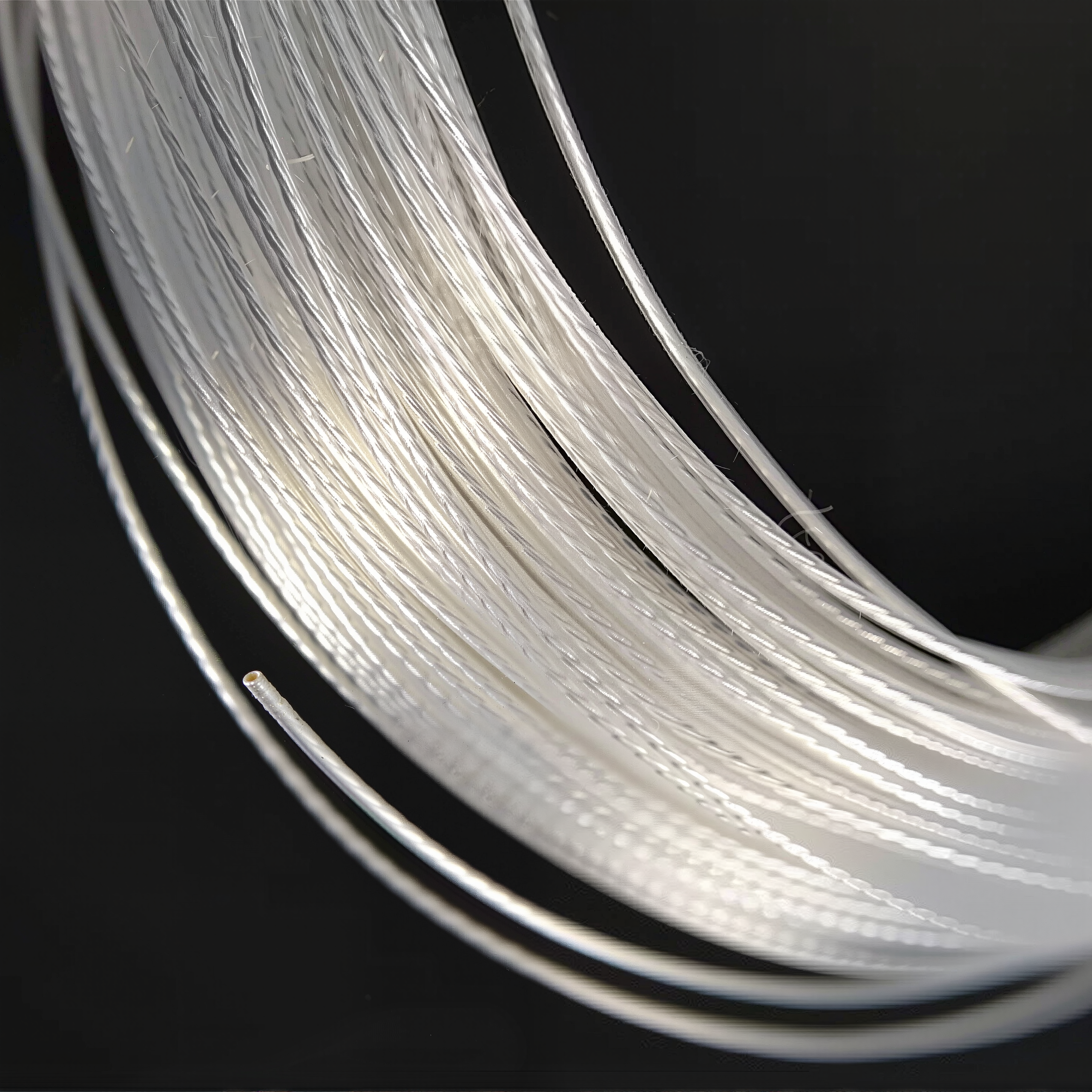
- Silver-plated copper wire:
- The silver layer is oxidation-resistant, avoiding the resistance increase caused by the oxidation of the copper conductor surface under high temperature (applicable to below 200°C).
- Nickel alloy wire:
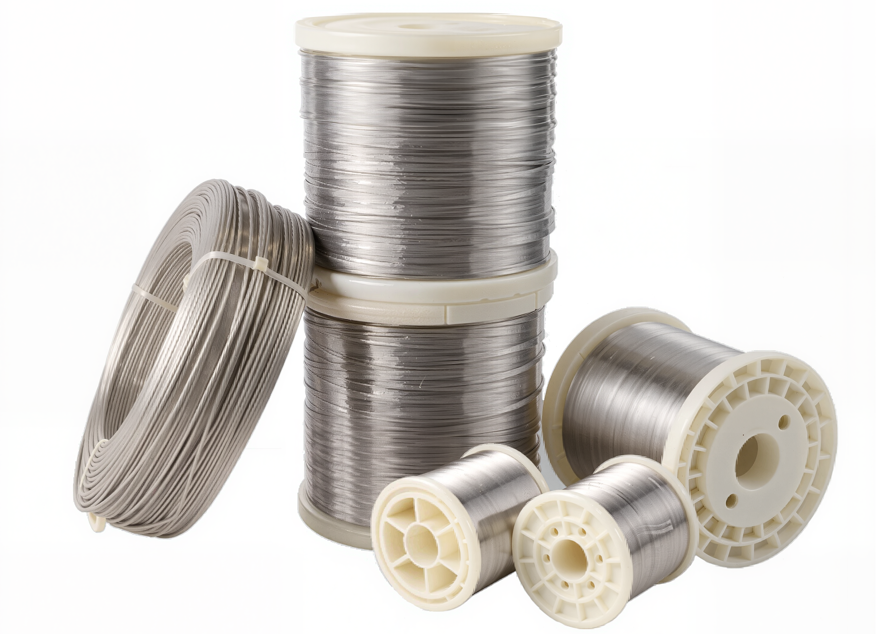
- Resistant to ultra-low temperatures (-200°C) without brittleness, used in deep space probes (e.g. Mars rover harnesses).
- Superconducting materials:
- Zero resistance at very low temperatures (e.g. liquid hydrogen fuel systems), currently in the experimental stage.
Insulation materials:
- PTFE (polytetrafluoroethylene):
- Long-term temperature resistance -200°C to +260°C, low coefficient of friction, used in engine compartment harnesses.
- PI (polyimide) film:
- Short-term temperature resistance up to 400°C, used in high-temperature areas of rocket bodies.
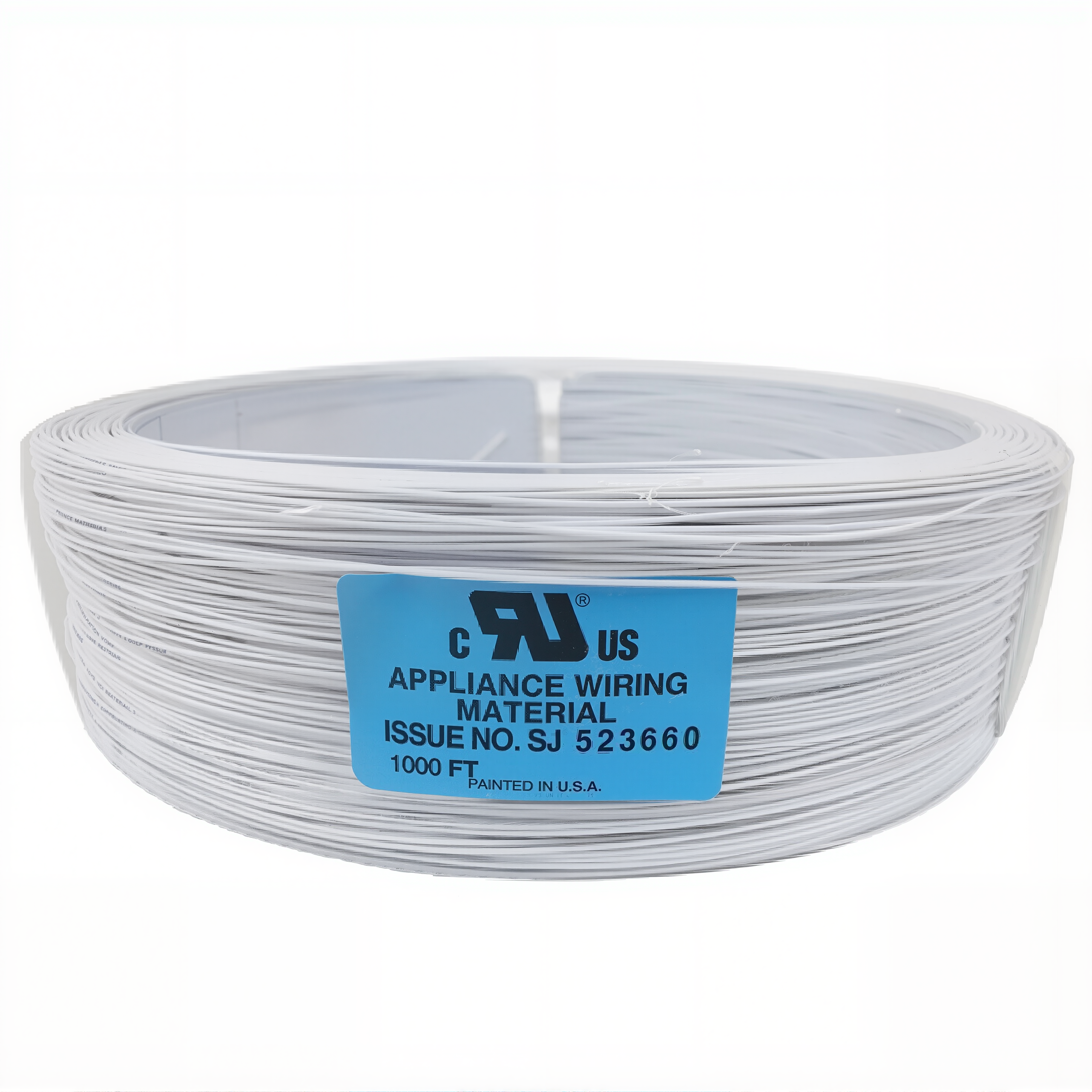
- Silicone rubber:
- Flexible and resistant to high and low temperatures (-60°C to +200°C), suitable for movable parts (e.g. satellite deployment mechanism).
1.2 Thermal Management Technologies
Thermal insulation design:
- Thermal insulation design:
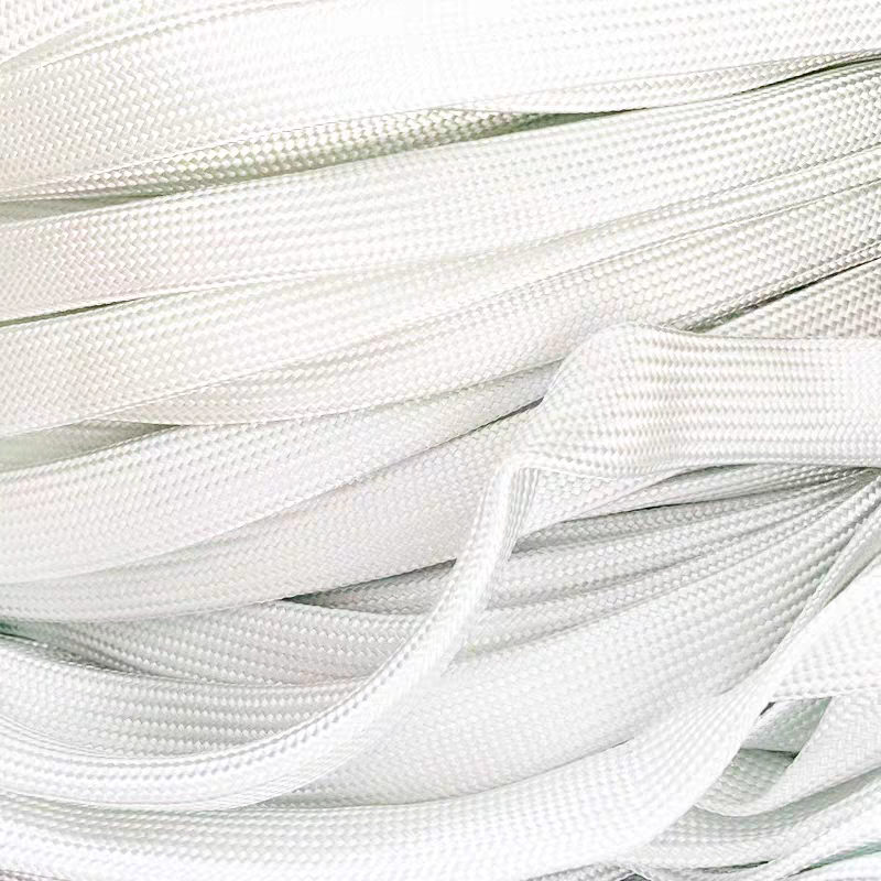
- Ceramic fibre braided sleeving or mica tape is used to wrap wire harnesses to insulate them from transient high temperatures (e.g. wire harnesses close to the engine).
- Vacuum insulation is used for satellite harnesses to reduce the transfer of extreme temperature differences in space.
- Thermal cycling adaptability:
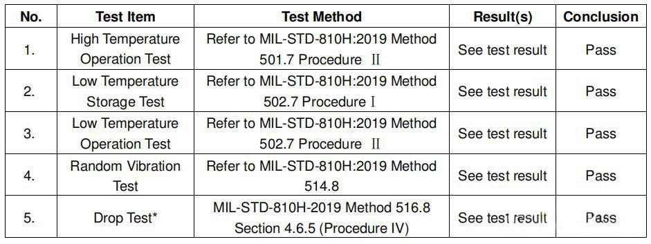
- Harnesses are required to pass MIL-STD-202G standard test (100 cycles from -55°C to +125°C) to ensure no cracking or peeling.
1.3 Extreme Case Analysis
- Supersonic aircraft wiring harness:
- The wiring harness of the SR-71 Blackbird reconnaissance aircraft needs to work stably between -60°C (high altitude) and 300°C (aerodynamic heating of the fuselage), and adopts PTFE insulation + silver-plated conductors.
- Mars Rover Wiring Harness:
- The wiring harness of the Mars Rover ‘Perseverance’ is required to withstand low temperatures of -120°C at night, using customised silicone insulation + nickel alloy conductors.
1.4 Testing Standards and Methods
- High-temperature aging test:
- The wiring harness is subjected to 260°C for 1,000 hours to test the change in insulation resistance (Standard: MIL-STD-810G Method 501.7).
- Low-temperature bending test:
- Bend the harness 100 times at -65°C to check the risk of conductor breakage (Standard: ECSS-Q-ST-70-60).
Conclusion
Extreme temperatures are the primary challenge in aerospace harness design, and need to be safeguarded through the triple combination of material science, thermal management processes, and rigorous testing.
In the future, with the development of deep space exploration and supersonic vehicles, the temperature resistance range will be further extended towards -270°C (deep space) to 500°C (hypersonic flight), driving the application of new materials (e.g. boron nitride insulating coatings).
2. Mechanical Stress and Vibration Resistance
In aerospace, wiring harnesses face mechanical challenges that go far beyond ordinary industrial scenarios.
The high manoeuvrability overload of fighter jets, the violent vibration of rocket launches, the continuous micro-vibration of satellites in orbit – these extreme working conditions require wiring harnesses to maintain stable signals and reliable connections under conditions of high-frequency vibration (2,000Hz), transient shocks (more than 50G), and long-term bending fatigue.
2.1 Vibration Resistance Design

(1) Vibration sources and hazards
- Vehicle engine vibration: Jet aircraft engine vibration frequency of up to 500 ~ 2000Hz, easy to lead to wiring harness connector loosening.
- Pneumatic turbulence: Transonic flight surface airflow impact triggered by random vibration (such as fighter wing harness).
- Rocket launch impact: Solid fuel booster ignition instant vibration acceleration exceeds 50G, which may cause wiring harness breakage.
Typical faults: increased contact resistance, shield wear, wire metal fatigue fracture.
(2) Anti-vibration key technologies
- Wire harness fixing and buffering:
- Adopt titanium alloy or composite material wire clips with intervals of ≤15cm (in line with MIL-STD-810G standards).
- Silicone shock absorbing sleeve or bellows is added to the key parts.
- Connector anti-loosening design:
- Thread locking connector (e.g. MIL-DTL-38999 series).
- Secondary locking mechanism (e.g. push-pull self-locking, snap-on terminals).
- Conductor reinforcement:
- Multi-stranded wires (e.g. 7 x 19 super flexible structure) to disperse stress.
- Critical nodes using ‘S-type’ alignment reserve buffer margin.
2.2 Impact and Overload Protection
(1) Extreme impact scenarios
- Fighter manoeuvre overload: 9G sustained acceleration (e.g. F-22 sharp turn).
- Landing impact: Civilian airliner landing instant impact of about 6G.
- Spacecraft Separation: Instantaneous impact triggered by exploding bolts during rocket stage separation.
(2) Impact resistant solutions
- Material Selection:
- Conductor: Silver-plated copper alloy (fatigue strength 30% higher than pure copper).
- Insulation: Polyetheretherketone (PEEK) and other high-strength polymers.
- Structure Optimisation:
- The harness backbone is ‘serpentine wired’ to absorb impact energy.
- The back of the connector is reinforced with epoxy resin.
- Tested and Verified:
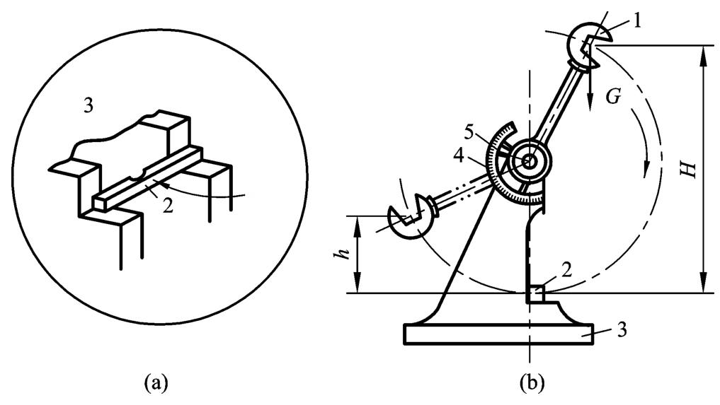
- Passed MIL-STD-883 method 2007.3 (mechanical shock test).
- Functions normally after simulating 50G/11ms half-sine wave impact.
2.3 Bending Fatigue Life Guarantee
(1) Highly flexible application scenarios
- Robotic arm harness: Space station robotic arm bends more than 1,000 times per day.
- Expandable satellite components: the harness at the hinge of the solar sail panel is repeatedly folded.
(2) Design to extend bending life
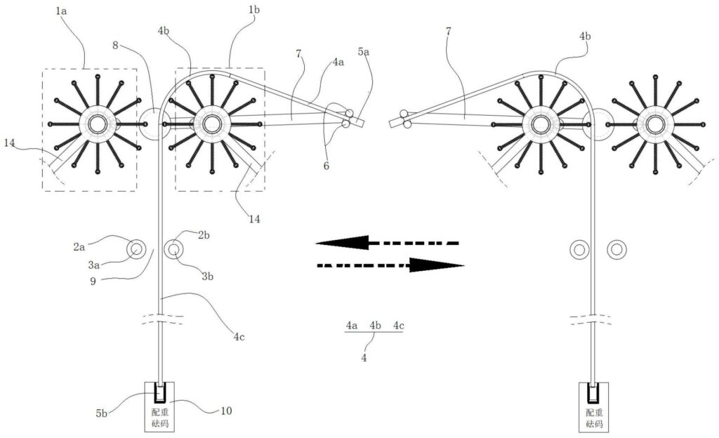
- Conductor structure: Adoption of 0.05mm extremely fine copper wire stranded in multiple strands (e.g. 19×41 structure).
- Insulation layer technology: TPU (thermoplastic polyurethane) is used instead of PVC for dynamic bending parts.
- Test standards: Passed MIL-W-16878E/15 (100,000 times bending cycle test).
2.4 Industry Standards and Certifications
- MIL-STD-810G: Method 514.7 (vibration test), Method 516.6 (shock test).
- SAE AS6070: Specification for bending fatigue test of aviation wire harnesses.
- ECSS-E-ST-10-03C: European Space Agency requirements for mechanical environmental adaptation of wire harnesses.
Conclusion
Mechanical adaptive design of aerospace wire harnesses is a combination of materials science, structural mechanics and process technology.
From nanoscale conductor optimisation to macrosystem fixation schemes, every detail is critical to mission success or failure.
With the development of deep space exploration and electric aviation, the anti-mechanical stress technology will continue to push the limits.
3. Vacuum and radiation environment
In the space environment, wire harnesses face a dual threat that is virtually non-existent on Earth: material failure due to high vacuum and performance degradation due to cosmic radiation.
These factors can lead to insulation cracking, signal interference, and even short circuits, directly threatening spacecraft safety. In this section, we will analyse in detail the damage mechanisms of the vacuum and radiation environments and the countermeasures.

3.1 Material Failure and Protection in Vacuum Environment
Challenge:
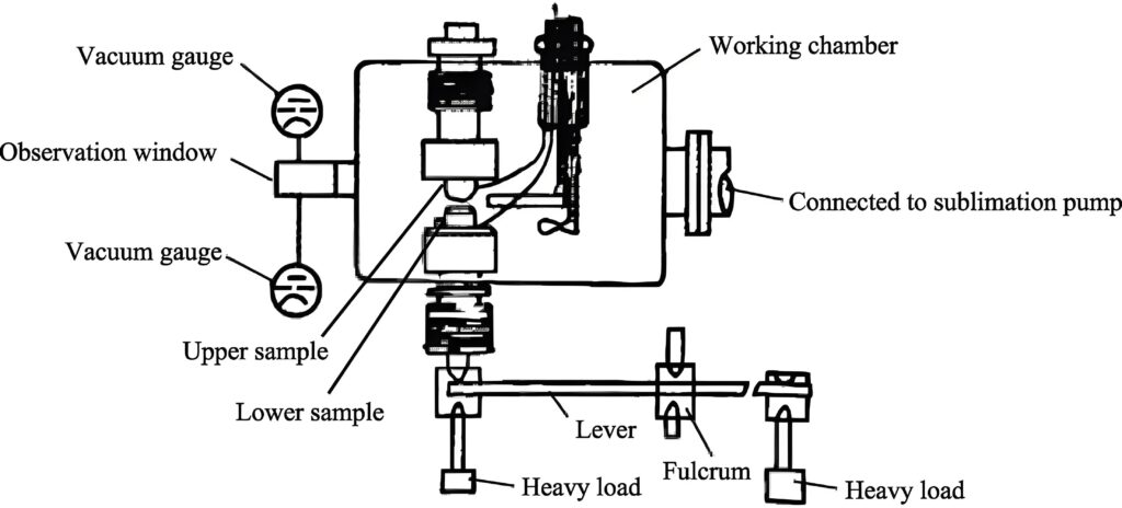
- Vacuum discharge (Paxing effect):
Surfaces of insulating materials are prone to arcing at low pressures, leading to breakdown (e.g., risk of satellite harnesses discharging in a 10-⁶ Pa vacuum). - Material Outgassing:
The release of volatile gases from organic materials that can contaminate optical equipment or condense into conductive films (e.g., silicone rubber releases xylene). - Cold soldering effect:
Sticking of metal surfaces in the absence of an oxide layer in a vacuum (e.g. failure of gold plating on connectors).
Solution:
- Low outgassing material selection:
▶ Insulation: PTFE (polytetrafluoroethylene), PI (polyimide), tested by NASA ASTM E595 (TML<1%, CVCM<0.1%).
▶ Adhesive: epoxy modified system, avoid silicone. - Vacuum protection design:
▶ Conductor is silver or nickel plated (anti-oxidation + lower contact resistance).
▶ Use of fully sealed connectors (e.g. MIL-DTL-83723 series with metal-glass sintered seals). - Test verification:
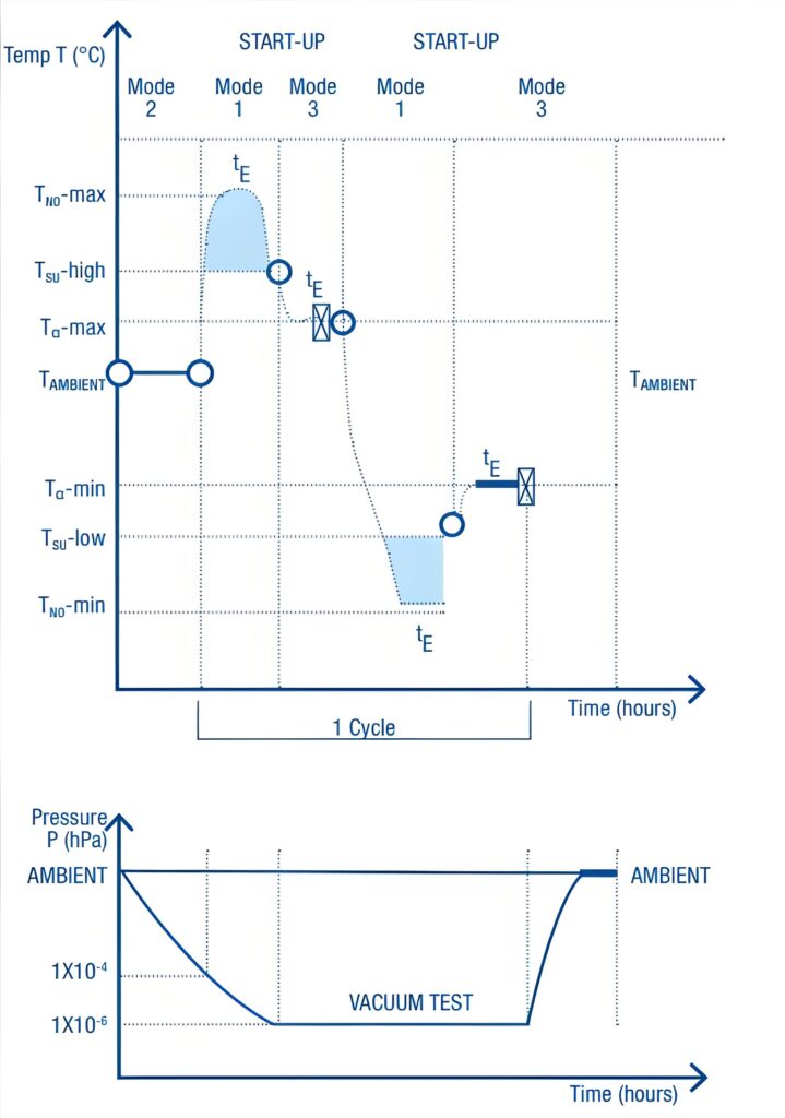
▶ Vacuum thermal cycle test (-120°C to +150°C, 10-⁴ Pa, 50 cycles).
3.2 Damage and reinforcement technology by cosmic radiation

Radiation type and effects:
| Types of radiation | Energy range | Hazards to the harness |
| Galactic cosmic rays | 1 GeV-1 TeV | Ionisation deterioration of insulating materials, increase in conductor resistivity. |
| Solar Proton Events | 10 MeV-100 MeV | Instantaneous dose leading to signal transmission anomalies (e.g., interruption of satellite communications). |
| Van Allen Belt Electrons | 0.1 MeV-10 MeV | Cumulative dose triggers polymer embrittlement (e.g. PTFE fracture). |
Radiation resistant reinforcement measures:
- Material preference:
▶ Insulation: ETFE (ethylene-tetrafluoroethylene copolymer) is 10 times more radiation resistant than PTFE.
▶ Shielding: Double-layer aluminised polyester film (thickness ≥ 50μm) combined with local lead shielding (critical signal lines). - Structural design:
▶ Redundant cabling is used (dual-channel signal transmission).
▶ Optical fibre instead of copper (EMP-resistant, e.g. SpaceX starship data bus). - Ground simulation tests:
▶ Cobalt-60 γ-ray irradiation test (total dose ≥ 100 krad, in accordance with ESA ESCC 22900).
3.3 Atomic Oxygen Corrosion and Protection
Low Earth Orbit (LEO, 200-700 km) is rich in atomic oxygen (AO), whose strong oxidising properties can erode polymer surfaces (e.g. Kapton film loss of 10 μm per year).
Protection options:
- Surface coating technology:
▶ Silicon-based coatings (e.g. SiO₂ coating, AO erosion rate reduced to 1%).
▶ Aluminium foil wrapping (standard practice for ISS harnesses). - Material substitution:
▶ Polyimide-nanoclay composite material selected (erosion rate reduced by 90%).
Conclusion
Vacuum and radiation environments are the ‘Mount Everest’ of aerospace harness design, requiring innovation from material molecular structure to system-level shielding.
With the development of deep space exploration and commercial spaceflight, new technologies such as radiation-resistant optical fibres and self-healing coatings will reshape the industry standard.
4. Corrosion resistance and chemical stability
In the aerospace field, the wire harness is exposed to salt spray, aviation fuel, hydraulic oil, rocket propellant (such as hydrazine), ozone, acidic atmosphere and other strong corrosive media for a long time.
Once corrosion occurs, the signal will be distorted, or a short circuit or even a catastrophic accident will occur.
Therefore, corrosion resistance and chemical stability is one of the core indicators of aerospace wiring harness design.
4.1 Corrosion Source Analysis and Risk Level
| Typical Scenarios | Damage to Wiring Harnesses | Risk Level | Salt Spray (Cl-) |
| Salt spray (Cl-) | Marine environment take-offs and landings, coastal airports | Copper conductor oxidation, cracked insulation | ★★★★★ |
| Aviation Fuel (JP-8) | Wiring harnesses near fuel tanks, engine compartments | Dissolved insulation, accelerated deterioration | ★★★★☆ |
| Hydraulic Oil (Skydrol) | Around Landing Gear/Rudder Hydraulics | Dissolves PVC sheathing, causes short circuits | ★★★★☆ |
| Hydrazine Propellant | Satellite/Rocket Fuel Line Areas | Corrodes metal terminals, embrittles plastic parts | ★★★★★ |
| Ozone (O₃) | High altitude flight (20km or more) | Rubber insulation cracking | ★★★☆☆ |
4.2 Key Protection Technologies
(1) Material selection – chemical inertness is king
- Conductor:
▶ Silver-plated copper wire (anti-sulfuration corrosion)
▶ Nickel-plated copper wire (fuel/hydraulic oil resistant)
▶ Titanium alloy conductor (specialised for hydrazine environment)
(2) Seal design – isolation from corrosive media
- Connector:
▶ MIL-DTL-5015 series fully sealed connectors are used (IP68 protection level).
▶ Metal shell + glass sintered seal (withstand pressure difference ±15psi). - Overall protection of the wiring harness:
▶ Heat-shrinkable sleeving + silicone potting (e.g. engine compartment harness).
▶ Metal braided mesh outer cladding (anti-mechanical abrasion + chemical penetration).
(3) Surface treatment technology
- Conductor plating:
▶Gold plating (high frequency signal lines, anti-oxidation + low contact resistance).
▶Tin plating (low cost universal solution, to be used with sealant). - Jacket coating:
▶Polyurethane coating (enhanced oil resistance).
▶Ceramic based coating (resistance to proton oxygen attack, for space harnesses).
4.3 Test and Verification Criteria
- Salt Spray Test:
▶ Standard: MIL-STD-810G Method 509.6
▶ Conditions: 5% NaCl solution, 35°C, continuous spray ≥ 500 hours.
▶ Qualified judgement: conductor resistance change ≤10%, insulation resistance ≥100MΩ.

- Chemical immersion test:
▶ Fuel oil (JP-8) immersion: 72 hours, volume expansion ≤5%.
▶ Hydraulic oil (Skydrol) test: ASTM D471, tensile strength retention ≥80%.
- Ozone aging test:
▶ Standard: ASTM D1149
▶ Conditions: 50pphm ozone concentration, 40°C, 72 hours.
▶ Requirements: No visible cracks (20x microscope inspection).
5. Fire prevention and flame retardant properties
In the aerospace industry, the fire resistance of wiring harnesses is directly related to flight safety.
A commercial airliner’s wiring harness can be hundreds of kilometres long, and in the event of a short-circuit or overheating, a poor-quality wiring harness can become a pathway for flames to spread.
Therefore, aerospace wiring harnesses must meet the stringent requirements of ‘non-flammable, low-smoke, and low-toxicity’ to ensure that they can buy valuable time for personnel escape and system emergency response in extreme situations.
5.1 Material selection: from basic insulation to active fire protection
Core material requirements:
- Insulation:
▶ Ceramicised silicone rubber: Forms a ceramic layer when exposed to fire, insulating against oxygen (still effective at temperatures >1000°C).
▶ XLPE (cross-linked polyethylene): cross-linking through irradiation to enhance the temperature resistance level (UL certification 125 ℃ ~ 150 ℃).
▶ PTFE (polytetrafluoroethylene): natural flame retardant, but need to pay attention to high temperature decomposition of toxic gases. - Jacket layer:
▶ Halogen-free flame-retardant polyolefin: meets Airbus ABD0031 standard, smoke transmission rate >60% when burning.
▶ Mica tape wrapping: used in engine compartment and other high temperature areas, temperature resistance > 800℃.
5.2 Test standards: simulate the most demanding fire scenarios
Aerospace wiring harnesses are required to pass a number of internationally authorised fire tests:
| Test Items | Standard Basis | Key Indicators | Simulation Scenario |
| Vertical Combustion Test | FAR 25.853 (Aviation) | Flame spread ≤ 15cm, self-extinguishing time ≤ 15 seconds | Short-circuit fire in cabin wires |
| 60° inclined combustion | ISO 2685 | Flame does not spread to the upper end of the wiring harness | High temperature ignition near the engine |
| Smoke Density Test | ABD0031 (Airbus) | Maximum Smoke Density Ds ≤ 200 (NBS Smoke Box Method) | Safeguarding of Cabin Visibility during Fire |
| Toxic Gas Analysis | BSS 7239 (Boeing) | CO < 100ppm, HCN < 50ppm (per gram of material) | Occupant Escape Safety in Confined Space |
| Fire Integrity Testing | MIL-W-22759E | Energised after Flame Impact (15 minutes) | Battle Damage or Engine Deflagration Emergency Power |
5.3 Design strategy: multi-layered fire barriers
- Passive protection:
▶ Segmental isolation: Wiring harnesses are segmentally wrapped in fireproof sleeving (e.g. ceramic fibre or Intumescent material) to form fireproof compartments.
▶ Metal conduit: Critical areas (e.g. near fuel pumps) are protected with stainless steel bellows. - Active protection:
▶ Thermal Coating: Coating expands at temperatures >150°C to isolate oxygen (e.g. 3M™ Fire Barrier Tape).
▶ Fuse protection: Integrated thermal fuse to automatically cut off the circuit in case of overheating (subject to DO-160G standard). - Redundant design:
▶ Dual circuit power supply + fire protection isolation to ensure the backup system is available in case of main circuit damage (e.g. A380 ‘fire partition’ design).
5.4 Industry Case: Iterating from Failure
- Challenge case:
A 2016 fire in a helicopter caused by a short-circuit in the wiring harness insulation deterioration, prompting the FAA to revise AC 25.869-1 to mandate a new fire-retardant coating. - Successful Solution:
Boeing 787 with Ceramifiable silicone rubber wiring harnesses that passed FAR 25.853 testing and reduced smoke during combustion by 40%.
6. Electromagnetic compatibility (EMC)

In aerospace systems, electromagnetic compatibility (EMC) is one of the core requirements to ensure reliable operation of wire harnesses.
Dense electronic equipment (e.g., radar, communication systems, flight control computers) inside the aircraft generates a complex electromagnetic environment, and the wiring harness, as a channel for the transmission of signals and power, must effectively suppress interference and prevent signal distortion or system failure.
6.1 Aerospace EMC Core Challenges
- High-frequency interference: RF noise generated by radar and radio equipment may be coupled into the wiring harness.
- Transient impulses: Transient high voltage shocks caused by lightning, electrostatic discharge (ESD) or power switching.
- Crosstalk problems: Mutual interference between high-frequency signals and low-voltage signals in multi-core wire harnesses.
- Radiation sensitivity: Cosmic rays in the space environment may induce electronic noise inside the harness.
6.2 Key Design Solutions
(1) Multi-layer shielding technology
- Braided copper mesh + aluminium foil composite shielding:
▶ Outer braided copper mesh (coverage ≥ 85%) to resist high frequency interference, inner aluminium foil to block low frequency magnetic field.
▶ Shielding effectiveness needs to be ≥90dB (passed MIL-STD-461G test). - Conductive Coating:
▶ The outer skin of the harness is coated with conductive paint (e.g. silver epoxy) to enhance full-band shielding.
(2) Grounding Optimisation
- 360° full perimeter grounding:
▶ Connectors with metal housing + ring spring contacts (e.g. MIL-DTL-38999) to ensure continuous grounding of the shield. - Segmented grounding strategy:
▶ Single-point grounding for high-frequency harnesses (to avoid ground loops) and multi-point grounding for power harnesses (to reduce impedance).
(3) Harness layout and grouping
- Partition isolation:
▶ High-voltage power lines, high-frequency signal lines, and sensitive analogue lines are wired in separate bundles with spacing ≥ 3 times the wire diameter. - Twisted-pair and coaxial wires are applied:
▶ Differential signals using twisted pair (e.g. CAN bus), GHz-level high-frequency signals using coaxial cable (e.g. SMA interface).
(4) Filtering and Transient Protection
- Magnetic ring filtering:
▶ Add a ferrite magnetic ring to the power line inlet to suppress common mode noise. - TVS diode:
▶ Lightning protection/ESD design (e.g. DO-160G Section 22 standard).
6.3 Industry Test Standards
Aerospace harness EMC must pass the following stringent tests:
- MIL-STD-461G:
▶ CE102 (conducted emission), RE102 (radiated emission), CS114 (conducted sensitivity). - DO-160G:
▶ Section 20 (RF sensitivity), Section 22 (lightning induced transients). - NASA-HDBK-4001:
▶ Radiated immunity requirements for space equipment harnesses.
6.4 Typical Application Examples
- Fighter aircraft avionics system:
▶ Silver-plated shielded wire harness + metal conduit is used to resist radar pulse interference. - Satellite communication harness:
▶ Double-layer shielding + fibre optic composite design to avoid mutual interference of starboard equipment. - Rocket on-board cable:
▶ Fully shielded armoured structure to prevent ignition electromagnetic pulse (EMP) from affecting the control system.
7. Typical application scenarios
Aerospace wiring harnesses are used in very different environments, and the performance requirements for harnesses vary from vehicle to vehicle.
| Application Scenarios | Core Challenges | Key Harness Characteristics | Representative Technologies |
| Civil Airliner | Fuel corrosion, long life | PTFE insulation, fire retardant | Boeing 787 Lightweight Harnesses |
| Fighter Aircraft | High G-force, Stealth Requirements | opper Clad Aluminium Conductors, Titanium Fixing | F-35 Hybrid Harnesses |
| Satellites | Vacuum Discharge, Radiation | Double Shielded ETFE, Gold Plated Terminals | Hubble Telescope Antiproton Oxygen Harnesses |
| Launch Vehicles | Vibration, Transient Temperature | Kevlar Sheathing, Stainless Steel Bellows | Falcon 9 Redundant Harnesses |
| Deep Space Probes | Ultra-low temperatures, sand and dust | Nickel alloy conductors, carbon fibre jacket | Trail Wear Harnesses |



Leave a Comment