Pressure Testing of Cable Harnesses for Deep-Sea Submersibles
Table of contents
▶ Environmental Pressure Testing
1. Hydrostatic Pressure Testing
Purpose
To validate the sealing performance and structural integrity of the cable harness under extreme deep-sea hydrostatic pressure (e.g., Mariana Trench, 11,000 meters depth, equivalent to ~110 MPa).
Test Methods
- Equipment: High-pressure chamber compliant with ISO 13628-5, filled with deionized water or synthetic seawater.
- Procedure:
- Place the cable harness in the chamber and pressurize to the target pressure (e.g., 120 MPa with safety margin) at 1 MPa/min.
- Maintain pressure for 24-72 hours to simulate long-term deep-sea operation.
- Inspect physical integrity and electrical performance after decompression.
Key Metrics
- Sealing: No leakage at connectors or jacket interfaces (detected by pressure sensors and visual inspection).
- Insulation Resistance: ≥100 MΩ after pressurization (measured by a megohmmeter).
- Deformation: Radial expansion rate of insulation layer ≤5% (recorded via laser scanning).
2. Thermal Cycling Testing
Purpose
To evaluate the material stability of the cable harness under alternating low-temperature deep-sea conditions (0-4°C) and high-temperature operation (e.g., motor heating up to 80°C).
Test Methods
- Equipment: Pressure chamber with integrated temperature control module (range: -10°C to 150°C).
- Procedure:
- Cycle temperature under high pressure (100 MPa): -5°C (30 min) →80°C (30 min), repeated 100 times.
- Monitor resistance variation, jacket cracking, and connector oxidation.
Key Failure Modes
- Thermal Fatigue: Micro-cracks caused by repeated expansion/contraction of the jacket.
- Contact Degradation: Increased impedance due to oxidation of metal connectors under temperature swings.
- Thermal Fatigue: Micro-cracks caused by repeated expansion/contraction of the jacket.
- Contact Degradation: Increased impedance due to oxidation of metal connectors under temperature swings.
3. Corrosion Testing
Purpose
To analyze the long-term corrosion effects of seawater chemistry (high salinity, low oxygen, microbes) on metal components and insulation materials.
Test Methods
- Solution Preparation: Acidic saline solution (pH=5.5, salinity 35‰) with sulfate-reducing bacteria (SRB) to simulate deep-sea conditions.
- Procedure:
- Immerse the cable harness in the solution within a pressure chamber (50 MPa) at 4°C.
- After 30 days, measure metal corrosion rate, insulation weight loss, and microbial colonization.
Evaluation Criteria
- Metal Components: Corrosion area ≤1% (per ASTM G1-03).
- Polymer Jacket: Weight loss ≤0.5% (per ISO 1817 aging test).
▷ The above tests comprehensively validate the reliability of cable harnesses in extreme deep-sea environments, providing critical data for design optimization.
▶ Mechanical Pressure Testing
1. Bending Fatigue Testing
Purpose
To verify the durability of the cable harness under repeated bending during deployment, retrieval, or seabed movement, preventing conductor breakage or jacket cracking due to mechanical fatigue.
Test Methods
- Equipment: Servo-driven robotic arm (programmable bending radius and frequency), high-precision fracture detection sensors.
- Procedure:
- Fix the cable harness on the robotic arm and perform cyclic bending at a preset radius (typically 5-10 times the cable diameter).
- Set cycles (e.g., 100,000 times) at a frequency of 10 cycles/minute.
- Monitor conductor resistance in real-time and inspect jacket cracks post-test.
Key Metrics
- Bending Radius: ≤10× cable diameter (to avoid excessive stress).
- Failure Criteria: Conductor resistance variation ≥10% or visible jacket cracks.

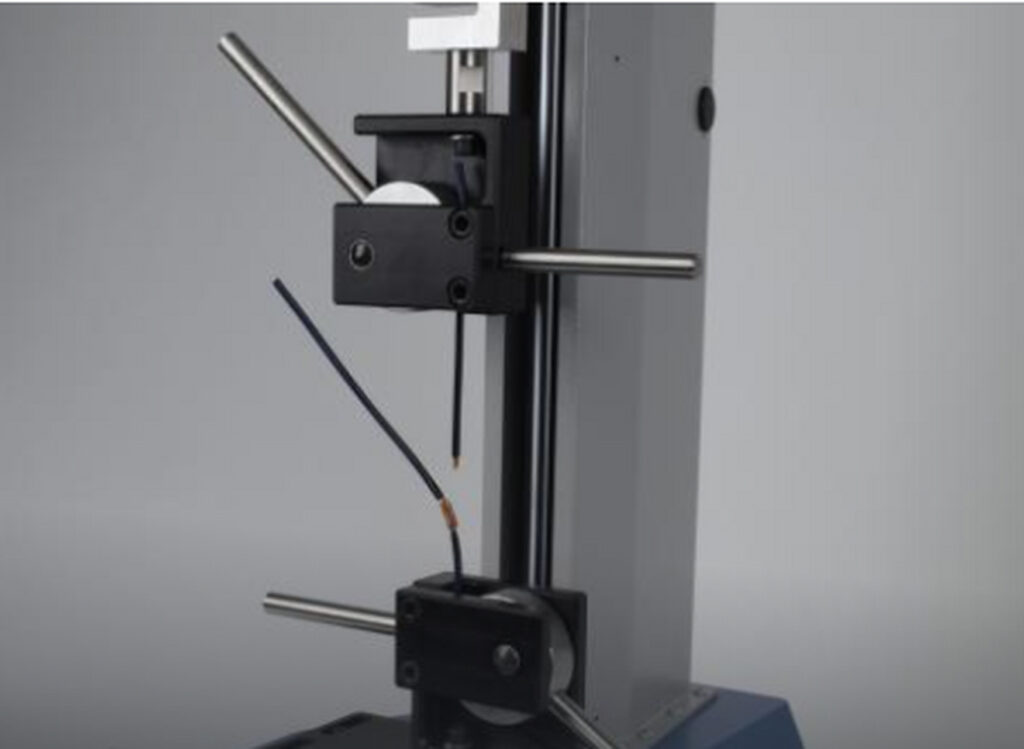
2. Tensile Testing
Purpose
To evaluate the tensile strength of the cable harness under deep-sea towing, current impact, or equipment weight, ensuring no conductor breakage or connector detachment.
Test Methods
- Equipment: Universal testing machine (capacity ≥50 kN) with a temperature chamber (simulating 0-30°C water).
- Procedure:
- Clamp both ends of the cable harness and apply axial tension at 5 mm/min until reaching the target load (e.g., 1.5× working load).
- Maintain maximum load for 5 minutes to observe breakage or slippage.
- Record breaking force and deformation curve.
Evaluation Criteria
- Tensile Strength: Breaking force of conductors and connectors ≥150% of design value (per IEC 61156-5).
- Deformation Limit: Total length variation ≤2% after stretching.
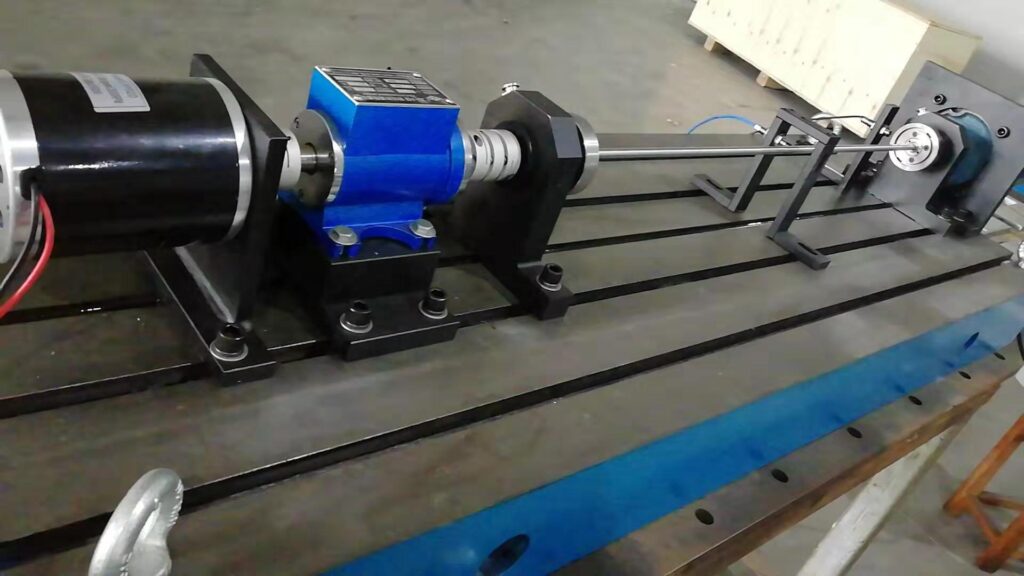
3. Torsion & Vibration Testing
Purpose
To simulate torsion and vibration during complex seabed movements, ensuring signal stability under dynamic mechanical stress.
Test Methods
Torsion Testing
- Equipment: Electric torsion tester (max torque 500 N·m).
- Procedure:
- Fix one end of the cable harness and apply ±180° reciprocating torsion at 1 Hz for 1000 cycles.
- Monitor conductor continuity and jacket delamination.
Vibration Testing
- Equipment: Triaxial vibration shaker (frequency range 5-2000 Hz, acceleration 20 g).
- Procedure:
- Set random vibration profiles per ISO 10816-3 (simulating underwater turbulence).
- Conduct vibration for 4 hours, checking connector loosening or signal loss.
Key Parameters
| Test Type | Parameters | Standard |
|---|---|---|
| Torsion Testing | Angle: ±180° | IEC 60512-28-100 |
| Vibration Testing | Acceleration: 20 g, 4h | ISO 10816-3 |
4. Impact Testing
Purpose
To validate the impact resistance of the cable harness during seabed contact or collision with obstacles.
Test Methods
- Equipment: Drop-weight impact tester (energy range 0-100 J).
- Procedure:
- Place the cable harness on a rigid base and impact it with a 10 kg hammer dropped from 1 m height.
- Repeat 5 times and inspect jacket damage or conductor short circuits.
Pass Criteria
- Appearance: No jacket rupture or metal deformation.
- Electrical Performance: Insulation resistance ≥50 MΩ post-impact.

▷ Mechanical pressure testing ensures the reliability of cable harnesses under dynamic and complex loads, guaranteeing long-term stable power and signal transmission for deep-sea explorers.
▶ Electrical Performance Testing
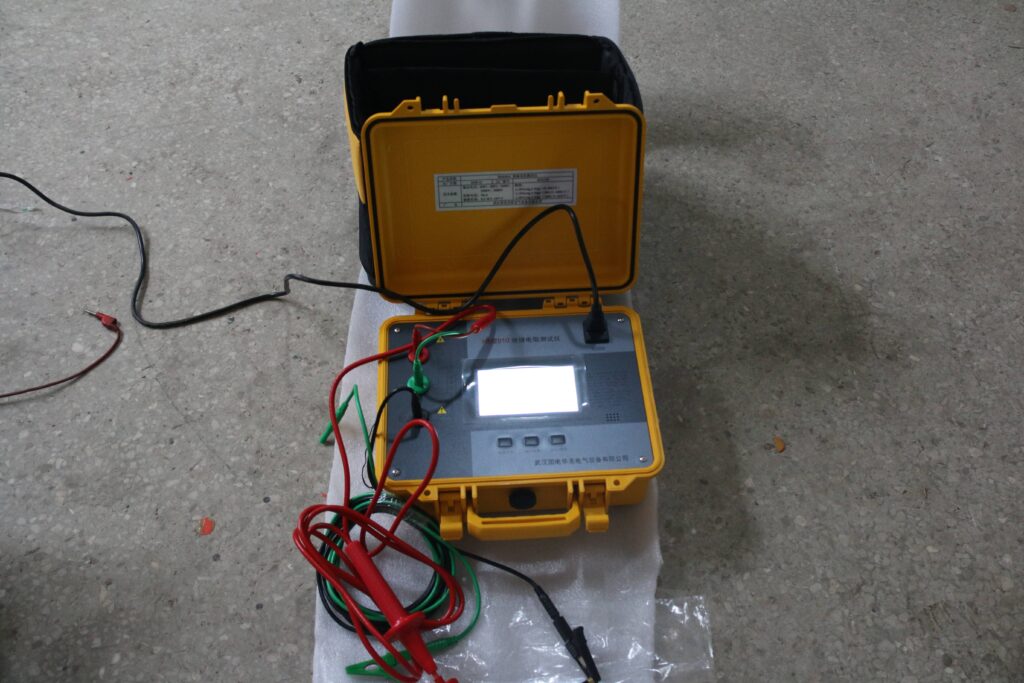
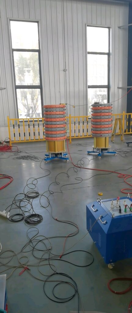
1. High-Voltage Insulation Resistance Testing
Purpose
To validate the reliability of insulation materials under high-pressure deep-sea conditions, preventing current leakage or short circuits.
Test Methods
- Equipment: High-pressure chamber integrated with a megohmmeter (range: 0.1 MΩ–10 GΩ) and DC voltage source (0–5000 V).
- Procedure:
- Place the cable harness in the chamber and pressurize to the target pressure (e.g., 110 MPa).
- Apply 500 V DC for 1 minute, measure insulation resistance between conductors and shielding.
- Repeat 3 times and take the minimum value as the final result.
Key Metrics
- Insulation Resistance: ≥100 MΩ (per IEC 60243-1).
- Stability: Measurement fluctuation ≤5% across three tests.
2. Conductivity & Signal Integrity Testing
Purpose
To ensure stable electrical conductivity and signal transmission quality under high pressure, vibration, and other harsh conditions.
Test Methods
- Conductivity Test:
- Measure conductor resistance with a 4-wire ohmmeter (resolution 0.001 Ω) under operational pressure.
- Compare resistance under ambient vs. high pressure; require ΔR ≤1%.
- High-Speed Signal Test:
- Use a vector network analyzer (VNA) to measure insertion loss (≤-3 dB) and return loss (≥-10 dB) at 10 GHz.
- Analyze 10 Gbps digital signal eye diagrams via oscilloscope; ensure eye height ≥0.3 UI and eye width ≥0.5 UI.
Evaluation Criteria
| Test Type | Parameters | Pass Criteria |
|---|---|---|
| Conductivity | Resistance variation (ΔR) | ≤1% |
| High-Frequency Signal | Insertion loss (10 GHz) | ≤-3 dB |
| Return loss (10 GHz) | ≥-10 dB | |
| Digital Signal | Eye diagram height | ≥0.3 UI |
| Eye diagram width | ≥0.5 UI |

3. Conductivity & Signal Integrity Testing
Purpose
To verify the cable harness’s ability to withstand transient overvoltage in high-pressure environments, avoiding insulation breakdown or arcing.
Test Methods
- Voltage Withstand Test:
- Apply 2500 V AC (or 2× rated voltage +1000 V) under 110 MPa for 1 minute.
- Check for breakdown or leakage current exceeding 1 mA (per IEC 60664-1).
- Arc Testing:
- Apply intermittent high-voltage pulses (e.g., 8 kV/1.2 μs) in a humid high-pressure environment.
- Record arc paths with high-speed cameras and analyze insulation self-recovery capability.
Pass Criteria
- Voltage Withstand: No breakdown or visible discharge.
- Arc Testing: Insulation material recovers to 90% of initial resistance within 30 seconds.
4. Grounding & Shielding Effectiveness Testing
Purpose
To evaluate the shielding effectiveness of the cable harness against electromagnetic interference (EMI) under high pressure and complex environments.
Test Methods
- Shielding Effectiveness:
- Measure signal attenuation (≥60 dB) across 1 MHz–10 GHz using a signal generator and spectrum analyzer in the pressure chamber.
- Grounding Continuity:
- Apply 50 A current and measure resistance between shielding layer and grounding point (≤0.1 Ω).
▷ Electrical performance testing ensures stable power transmission and signal quality in extreme deep-sea environments, providing reliable data and energy pathways for the submersible.
▶ Long-Term Stability Testing
1. Continuous Load Testing
Purpose
To simulate the cable harness’s ability to sustain continuous electrical and mechanical loads during long-term deep-sea missions (e.g., months to years), detecting performance degradation or latent failures.
Test Methods
- Equipment: Pressure chamber (integrated temperature/pressure control), dynamic load simulator.
- Procedure:
- Operate the cable harness at full load (e.g., rated current + high-speed signal transmission) under target pressure (110 MPa) and low temperature (4°C).
- Conduct testing for 30-90 days, daily logging conductor resistance, insulation resistance, and jacket deformation.
- Perform comprehensive performance checks (including signal integrity) every 7 days.
Key Metrics
- Resistance Stability: Conductor resistance variation ≤2% (vs. initial value).
- Insulation Degradation: Insulation resistance decline rate ≤5%/month.
2. Accelerated Aging Testing
Purpose
To predict the service life of the cable harness in deep-sea environments by accelerating material aging through intensified stress (high temperature, humidity, and pressure).
Test Methods
- Equipment: Multi-stress aging chamber (pressure 0–150 MPa, temperature -10–150°C, humidity 0–100% RH).
- Procedure:
- Expose the cable harness to accelerated conditions (e.g., 80°C, 100 MPa, 95% RH) for 1000 hours.
- Sample every 240 hours to measure jacket hardness, conductor oxidation, and insulation dielectric strength.
Evaluation Models
| Acceleration Factor | Parameters | Standard |
|---|---|---|
| Arrhenius Model | Reaction rate doubles per 10°C rise | Arrhenius Equation |
| Pressure-Life Model | 15% life reduction per 10 MPa pressure increase | ISO 16750-4 |
3. Cyclic Pressure Testing
Purpose
To verify the fatigue resistance of the cable harness under repeated pressure cycles (e.g., frequent submersible ascent/descent).
Test Methods
- Equipment: Automated pressure cycling chamber (pressure change rate ≤5 MPa/s).
- Procedure:
- Cycle pressure between 0 MPa →110 MPa →0 MPa, 50 cycles/day.
- After 30 days, inspect sealing integrity, conductor breakage, and jacket delamination.
Pass Criteria
- Sealing Integrity: No leakage post-cycling (pressure sensor verification).
- Mechanical Damage: Jacket delamination area ≤1 mm² (microscopic imaging analysis).
4. Lifetime Prediction & Failure Analysis
Purpose
To build lifetime prediction models based on long-term test data, identifying weak points for design optimization.
Analysis Methods
- Weibull Distribution Model: Analyze failure time data to calculate reliability (e.g., R(t)=99.9%@10 years).
- Finite Element Simulation: Simulate material creep and fatigue crack growth under long-term stress via ANSYS.
- Destructive Analysis: Dissect aged cables to observe conductor oxidation paths and microscopic insulation cracks.
Key Outputs
| Analysis Type | Output Parameters | Optimization Direction |
|---|---|---|
| Weibull Analysis | Shape parameter β=1.2, scale parameter η=15 years | Enhance jacket fatigue resistance |
| Finite Element Simulation | Max stress concentration at connectors | Optimize connector geometry |
▷ Long-term stability testing quantifies the durability of cable harnesses in extreme deep-sea environments, providing scientific foundations for mission planning, maintenance strategies, and material selection.
▶ Safety & Redundancy Testing
1. Failure Mode and Effects Analysis (FMEA)
Purpose
To identify single-point failure modes (e.g., conductor breakage, insulation breakdown) and their system-wide impacts, guiding redundancy design optimization.
Test Methods
- Procedure:
- List all potential failure modes (e.g., connector detachment, jacket cracking).
- Evaluate occurrence (O), severity (S), and detectability (D) to calculate Risk Priority Number (RPN=O×S×D).
- Design redundancies or safeguards for high-RPN items (RPN≥100).
Key Outputs
| Failure Mode | RPN | Mitigation |
|---|---|---|
| Conductor Breakage | 120 | Add parallel redundant conductors |
| Connector Leakage | 90 | Dual O-ring sealing design |
2. Redundant Circuit Switching Testing
Purpose
To validate that redundant circuits can seamlessly take over within specified time limits upon primary circuit failure, ensuring uninterrupted operation.
Test Methods
- Equipment: Fault simulator, high-speed data logger (sampling rate ≥1 MHz).
- Procedure:
- Artificially trigger primary circuit failure (e.g., power/signal cutoff).
- Measure redundant circuit activation time and transient voltage fluctuation.
- Repeat 20 times to calculate success rate and average switching time.
Pass Criteria
- Switching Time: ≤10 ms (real-time control system requirement).
- Voltage Fluctuation: ≤±5% of rated voltage.
3. Fault Injection Testing
Purpose
To evaluate system-wide fault tolerance by simulating extreme scenarios (e.g., simultaneous multi-circuit failures).
Test Methods
- Procedure:
- Inject combined faults (e.g., main power loss + signal short circuit).
- Monitor system degradation modes and self-recovery functions (e.g., auto-switching to backup power).
- Record key parameters: recovery time, data packet loss rate.
Evaluation Criteria
| Fault Type | Max Recovery Time | Max Packet Loss Rate |
|---|---|---|
| Single-Circuit Failure | 10 ms | 0% |
| Dual-Circuit Failure | 50 ms | ≤0.1% |
4. Safety Margin Verification
Purpose
To quantify safety margins (e.g., electrical, mechanical) of the cable harness design, ensuring temporary safe operation beyond rated conditions.
Test Methods
- Electrical Margin:
- Apply 1.5× rated voltage (e.g., 750 V for a 500 V design) for 1 minute, check insulation breakdown.
- Mechanical Margin:
- Apply 2× working load to stretch the harness for 5 minutes, measure permanent deformation rate (≤3%).
5. Emergency Power-Off (EPO) Testing
Purpose
To verify the cable harness’s ability to rapidly cut off power during emergencies, preventing fault propagation or equipment damage.
Test Methods
- Procedure:
- Simulate a short circuit or overload to trigger EPO signal.
- Measure shutdown response time (from fault detection to zero current).
- Inspect post-shutdown insulation recovery (e.g., no residual charge).
Pass Criteria
- Response Time: ≤5 ms (per IEC 60947-2).
- Insulation Recovery: Insulation resistance ≥10 MΩ within 1 second post-shutdown.
▷ Safety and redundancy testing significantly enhance the survivability of cable harnesses under extreme fault scenarios, delivering fail-safe core assurance for deep-sea submersibles.
▶ Testing Standards & Certification
1. International Standards
ISO 13628-5
Scope: Design and testing of control systems for subsea production systems, covering hydrostatic pressure, thermal cycling, and mechanical performance of cable harnesses.
Key Requirements:
- Sealing integrity at 110 MPa pressure (no leakage).
- Thermal cycling range: -10°C to 80°C, ≥100 cycles.
Test Methods: ISO-certified high-pressure chamber for deep-sea simulation.
IEC 60512-28-100
Scope: Mechanical testing of electrical connectors, including bending, tensile, and torsion of cable harnesses.
Key Requirements:
- Bending radius ≤8× cable diameter, ≥25,000 cycles.
- Tensile strength ≥200 N (single-core harness).
Test Methods: Servo-driven robotic arms and universal testing machines.
IEEE 1580
Scope: Electrical performance and fire safety requirements for marine cables and harnesses.
Key Requirements:
- Insulation resistance ≥100 MΩ (500 V DC test).
- Flame resistance: Pass vertical flame test (UL 1581).
Test Methods: Megohmmeter and flame test chambers.

2. National Standards
China GB/T 2423
Scope: Environmental testing for electrical/electronic products, including temperature, humidity, and salt spray tests.
Key Requirements:
- Salt spray test: No metal corrosion after 96 hours (GB/T 10125).
- Damp heat test: Insulation resistance ≥10 MΩ at 40°C/93% RH.
USA MIL-STD-810
Scope: Mechanical and environmental reliability testing for military equipment, applicable to extreme-condition validation of deep-sea cable harnesses.
Key Requirements:
- Vibration test: 20-2000 Hz random vibration at 15 g.
- Shock test: Half-sine shock (40 g/11 ms).
3. Industry Standards
API 17F
Scope: Subsea production control systems, specifying redundancy design and fail-safe requirements.
Key Requirements:
- Redundant circuit switching time ≤10 ms.
- Single-point failures must not cause system shutdown.

DNVGL-RP-0034
Scope: Long-term durability assessment of subsea cables/harnesses (DNV GL standard).
Key Requirements:
- Lifetime prediction models based on accelerated aging data (Arrhenius equation).
- Annual aging rate ≤3%.

4. Certification Process
Steps:
- Application Submission: Submit design documents and test plans to certification bodies (e.g., DNV GL, ABS).
- Testing Execution: Complete full-scope tests (e.g., ISO 13628-5, IEC 60512) at accredited labs.
- Document Review: Verify test reports, material lists, and quality control records.
- On-Site Audit: Inspect manufacturing processes and quality management systems.
- Certification Issuance: Obtain certification marks (e.g., DNV GL Type Approval).
- Periodic Renewal: Renew certification every 3 years to ensure ongoing compliance.
5. Certification Bodies
Key Agencies:
| Agency | Chinese Name | Expertise |
|---|---|---|
| DNV GL | Norwegian Class Society | Marine engineering & deep-sea equipment |
| ABS | American Class Society | Ship & subsea system certification |
| CCS | China Class Society | Chinese deep-sea equipment standards |
▷ Compliance with these standards and certifications ensures global technical recognition of deep-sea cable harnesses, guaranteeing design, manufacturing, and testing reliability.
Pressure testing of cable harnesses for deep-sea submersibles is a critical component in ensuring their stable operation under extreme environmental conditions.
Through comprehensive validation of environmental, mechanical, electrical, long-term stability, and safety redundancy performance—combined with adherence to international standards and stringent certification processes—the design and manufacturing of these harnesses demonstrate exceptional reliability in overcoming challenges such as high pressure, low temperatures, corrosion, and dynamic loads.
These tests not only provide technical assurance for the success of deep-sea exploration missions but also establish a robust engineering foundation for humanity’s quest to explore the uncharted realms of the ocean.
Leave a Comment