Lightning Protection Design for Traffic Signal Light Wire Harnesses
Lightning strikes pose a critical threat to the stable operation of traffic signal systems. The immense energy generated can readily invade through power and signal wire harnesses, causing equipment damage and traffic paralysis. For lightning protection design of wire harnesses, a <strong>three-pronged integrated protection system</strong> encompassing <strong>external direct-strike protection, induced lightning surge suppression, low-resistance grounding, and precision construction</strong> must be established. This forms a solid foundation for ensuring the safe and reliable operation of urban traffic signals.
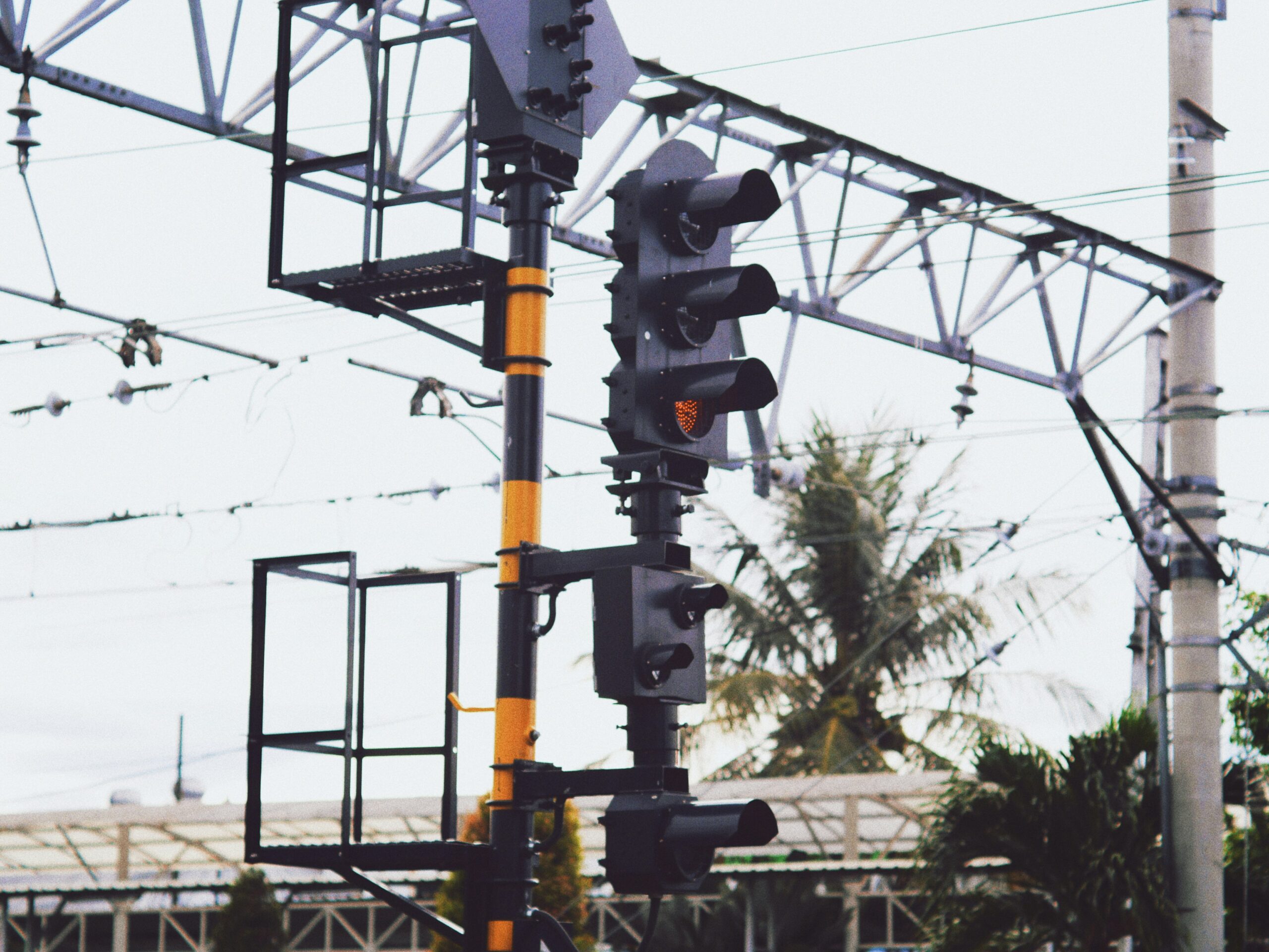
I. External Direct-Strike Protection (For Wire Harnesses and Adjacent Structures)
External direct-strike protection forms the first line of defense in the lightning protection system. Its core objectives are to prevent lightning from directly striking supporting structures (poles, cantilevers) and wire harnesses of traffic signals, or to safely and rapidly channel massive lightning currents into the ground when direct strikes occur. This minimizes the risk of lightning currents invading backend control systems and equipment through wire harnesses. This design directly determines the system’s survivability during extreme thunderstorms.
Key design elements include:
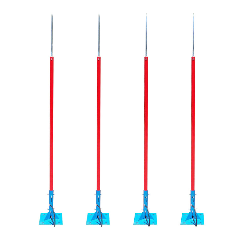
① Air Termination System (Lightning Rods/Conductors/Natural Terminations):
Function: Actively “attracts” or intercepts direct lightning strikes, serving as the primary contact point for lightning current.
Design Specifications:
- Positioning & Height: Must be installed at the highest point of the protected area. For single poles, one or multiple rods (based on protection zone calculations) are typically mounted atop. For signal lights with cantilevers, rods should be placed at the highest end of the cantilever. Large gantries may require continuous conductors along the top edge.
- Protection Zone Calculation: Must strictly comply with lightning protection standards (e.g., Rolling Sphere Method or Protection Angle Method in GB 50057). Ensure calculated zones fully cover:
- Entire pole structure (including attached signal fixtures and access doors).
- Cantilever assembly (from pole connection to furthest point).
- Ground control cabinets (if outside the pole’s protection zone).
- Critical: Wire harness routing (especially sections entering/exiting control cabinets and upper runs along poles/cantilevers) must be within the effective protection zone.
Materials & Specifications: Typically hot-dip galvanized round steel (Ø≥16mm) or steel pipe (Ø≥25mm, wall thickness≥2.5mm) for superior conductivity and corrosion resistance. Specifications must meet expected lightning current discharge requirements.
Natural Terminations: If poles, cantilevers, or cabinet enclosures are made of metal (e.g., steel) with thickness meeting standards (typically ≥4mm) and exhibit electrical continuity (reliable welding), they may serve as natural terminations, eliminating additional rods. This simplifies structures but requires rigorous thickness and continuity verification.
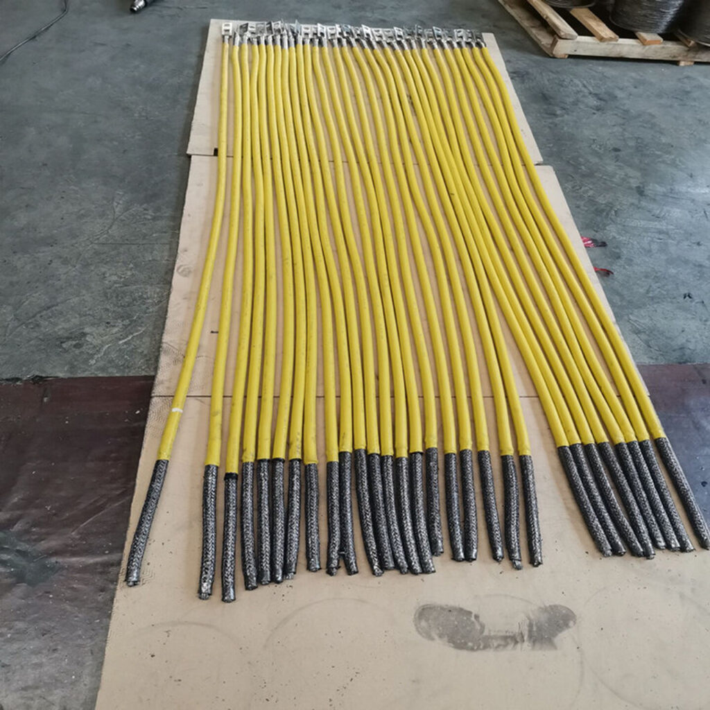
② Down Conductor System:
Function: Provides a low-impedance, reliable path to safely conduct tens or hundreds of kiloamperes of intercepted lightning current to the grounding system.
Design Specifications:
- Quantity & Layout: Minimum two down conductors (per GB 50057), symmetrically and evenly distributed around protected objects (e.g., poles). For taller poles (>12m) or large structures, increase density (e.g., ≤18-25m intervals) to reduce electromagnetic interference per conductor.
- Materials & Specifications: Prefer hot-dip galvanized round steel (Ø≥10mm) or flat steel (cross-section ≥80mm², thickness ≥4mm). Metallic poles/cantilevers meeting thickness requirements may serve as natural down conductors (most effective), but electrical continuity must be ensured:
- Inter-pole sections connected via reliable welding or bonding conductors (≥50mm² copper or equivalent).
- Flange joints secured with bolts and lock washers, supplemented by bonding jumpers if necessary.
- Routing: Paths must be short and straight with large-radius bends to minimize impedance/inductance for rapid current dissipation.
- Separation from Harnesses: Maintain safe distance (≥1.5-2m) between down conductors (independent or structural) and signal wire harnesses (especially signal lines). This prevents side-flash: High-potential differences during lightning discharge may breach air/cable insulation, introducing high voltage into harnesses. If distance is unattainable, harnesses must be enclosed in fully grounded metal conduits/raceways for electromagnetic shielding.
③ Shielding & Physical Isolation (For Wire Harnesses):
Function: Prevents side flashes from nearby objects (e.g., trees, buildings) or strong electromagnetic coupling to harnesses—even within protection zones. Provides physical protection and is critical for blocking side-flash and induced overvoltages from down conductors.
Design Specifications:
- Full-Length Metal Conduit/Raceway Shielding:
- Mandatory Requirement: All harnesses entering/exiting control cabinets (power, signal, detector, network cables) must be routed through metal conduits (e.g., hot-dip galvanized steel, stainless steel) or enclosed metal raceways.
- Electrical Continuity: Conduits/raceways must maintain full electrical continuity. Sections joined via threaded couplings, welded sleeves, or anti-loosening connectors.
- Reliable Grounding: Conduits/raceways grounded at both ends (cabinet entry/exit and terminal equipment) and at intervals (≤20-25m) using conductors (≥6mm² copper or equivalent) bonded to nearest grounding point or down conductor. Critical for draining induced currents and maintaining shielding. Connections must be robust and corrosion-resistant.
- Underground Installation:
- Minimum burial depth ≥0.7m (soil provides natural shielding).
- Always use metal conduits for mechanical and rodent protection.
- Use reinforced steel conduits or concrete encasement under roadways.
- Overhead Installation (Avoid if Possible):
- Avoid overhead routing due to high exposure risk.
- If unavoidable (e.g., crossing intersections), use cables with metallic armor/shielding.
- Support strands grounded at both ends. Cable shields grounded terminally.
- Maximize distance from air terminations/down conductors.
- Harness Routing Planning:
- Route harnesses close to poles/structures to leverage inherent shielding.
- Absolutely prohibit parallel/adjacent routing between harnesses (even in conduit) and independent down conductors.
- Avoid areas prone to direct strikes or water accumulation.
Summary (External Direct-Strike Protection):
External direct-strike protection is foundational for traffic signal lightning resilience, adhering to the “Intercept, Channel, Isolate” principle:
- Intercept: Air termination systems divert potential strikes away from critical components.
- Channel: Low-impedance down conductors safely dissipate massive currents to earth.
- Isolate: Full-length grounded metal conduits, safe distancing, and optimized routing physically/electromagnetically isolate harnesses from high-current paths and potential gradients.
This design must strictly follow national/industry standards (e.g., GB 50057) with site-specific calculations to ensure efficacy. Any oversight may compromise the entire protection system.
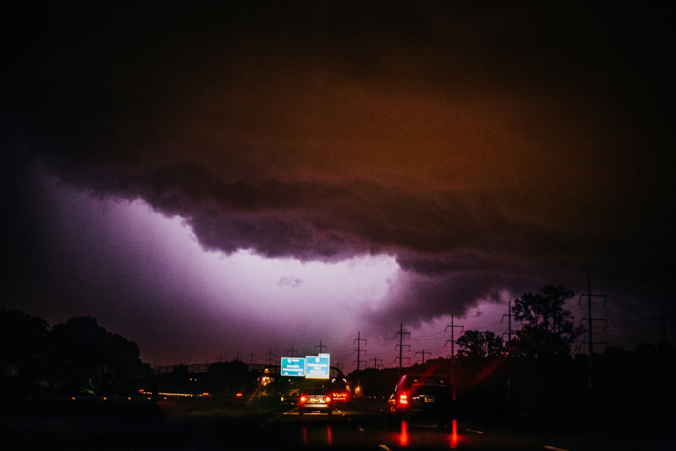
II. Protection Against Induced Lightning/Surge Overvoltages (For Overvoltages Introduced via Wire Harnesses)
While induced lightning doesn’t directly destroy equipment, it is the most frequent and insidious threat to traffic signal systems. When lightning currents pass through nearby objects (e.g., air terminals, down conductors, or cloud-to-cloud discharges), the resulting intense electromagnetic fields induce surge overvoltages (kV to tens of kV) on metallic lines. These overvoltages invade systems through power, signal, and communication harnesses, exceeding electronic components’ withstand limits and causing equipment damage, data corruption, or system failure. This design constitutes the critical defense line for protecting core electronics (controllers, detectors, communication modules).
① Multi-Stage Surge Protective Device (SPD) Deployment (Core Diversion Path)
Design Philosophy: Implement “coarse-to-fine” graded protection by installing SPDs with varying current-handling capabilities and residual voltages at critical entry points.
Protection Levels & Configuration:
- Stage 1 (Coarse Protection – Diverts Bulk Energy):
- Location: Main power supply entrance (upstream of control cabinet main switch).
- Function: Diverts >80% of surge energy from direct strikes or strong nearby induction.
- Selection:
- Type: Prioritize switch-type SPDs (e.g., spark gaps) for high current handling (Iimp ≥ 50-100kA, 10/350μs) and low leakage. Use hybrid SPDs (switch-type + voltage-limiting MOV) in high soil resistivity or severe thunderstorm areas.
- Key Parameters:
- Impulse Current Iimp (10/350μs): ≥ 25kA (≥50kA typical for LPL I/II).
- Voltage Protection Level Up: ≤ 4kV (< downstream equipment insulation).
- Max. Continuous Operating Voltage Uc: ≥ 385V (accommodates grid fluctuations).
- Stage 2 (Intermediate Protection – Further Voltage Limiting):
- Location: Internal power distribution unit (downstream of breakers, upstream of equipment inputs).
- Function: Diverts residual Stage 1 energy and locally induced surges.
- Selection:
- Type: Voltage-limiting SPDs (MOV-based) for nanosecond response.
- Key Parameters:
- Nominal Discharge Current In (8/20μs): ≥ 40-80kA.
- Max. Discharge Current Imax (8/20μs): ≥ 80-120kA (≥2×In).
- Up: ≤ 2.5kV (coordinated with Stage 1, < equipment withstand).
- Uc: ≥ 385V.
- Stage 3 (Fine Protection – Equipment Port Level):
- Location: Immediately at sensitive equipment inputs (controller PCBs, comms gateways, LED drivers).
- Function: Absorbs residual energy; provides ultra-low Up as final barrier.
- Selection:
- Type: Precision voltage-limiting SPDs (TVS diodes [picosecond response] or low-capacitance MOVs).
- Key Parameters:
- In (8/20μs): 5-20kA.
- Up: ≤ 1.5kV (< equipment port insulation).
- Uc: Matches equipment voltage (e.g., 12/24V DC).
Signal/Comm Line Protection (Essential & Independent):
- Location: All signal lines at control cabinet entry points (RS485, Ethernet, serial ports, detector inputs, fiber-copper media converters).
- Risk: Low operating voltages (5-24V) and high data rates increase vulnerability.
- Selection:
- Dedicated Signal SPDs: Match interface (RJ45/DB9/terminal), signal type (analog/digital), data rate (≥1.5× operating rate), voltage.
- Key Parameters:
- Protection Modes: Full line-to-line (differential) & line-to-ground (common mode).
- Insertion Loss: ≤ 0.5dB (preserve signal integrity).
- Data Rate Support: ≥ Actual rate × 1.5 (e.g., ≥150Mbps for 100Mbps Ethernet).
- Current Rating (8/20μs): ≥ 5kA (common mode) / ≥ 1kA (differential mode).
- Residual Voltage: ≤ Equipment withstand (e.g., ±15kV contact discharge for RS485).
- Examples:
- Ethernet: RJ45 Gigabit SPDs.
- RS485 Bus: DIN-rail SPDs with A/B/GND protection.
- Vehicle Detector Loops: Low-frequency, high-sensitivity SPDs.
SPD Deployment Critical Requirements:
- Energy Coordination: Adjacent SPDs require energy coordination via:
- Impedance Decoupling: Natural line impedance (≥10m cable length).
- Active Decoupling: Series decoupling inductors.
- Decreasing Up Values: Ensure Up₁ > Up₂ > Up₃ for voltage gradient.
- Grounding Conductors (“Short, Straight, Robust”):
- Length: ≤ 0.5m (critical for Stage 1; +1kV residual per 0.5m increase).
- Cross-Section: Stage 1 ≥16mm² (Cu), Stage 2/3 ≥6-10mm², Signal ≥2.5-4mm².
- Routing: Avoid coiling; connect directly to Equipotential Bonding Bar (PEB).
② Shielding & Grounding System (Equalize Potentials, Suppress Coupling)
Shield Termination at Both Ends:
- Principle: Shields (armor, braid, foil) of all shielded cables must be grounded at control cabinet entry and equipment end/remote ground point.
- Termination Method:
- Avoid “Pigtails”: Use 360° shield clamps or connector metal shells.
- Cabinet Handling: Peel shield and crimp with copper tape/ferrule to PEB.
Conduit/Raceway Shielding & Grounding Enhancement:
- Full Continuity: Metal conduits/raceways must be electrically continuous (bonding resistance ≤0.03Ω).
- Multi-Point Grounding: Ground at ≤20m intervals (≥6mm² Cu wire) besides endpoints.
Equipotential Bonding (Critical!):
- Goal: Eliminate transient potential differences among metal components.
- Implementation:
- Main PEB: Heavy copper bar (e.g., 30×5mm) mounted on insulators.
- Star Topology: Connect all grounding points to PEB via individual short wires:
• SPD ground terminals
• Cabinet frame
• Cable shield consolidation point
• Conduit entry sleeves
• Equipment ground terminals
• Grounding system feeder - Insulated Mounting: PEB isolated from cabinet, single-point connection to earth grid.
③ Wiring Segregation & Loop Control (Reduce Induction Paths)
Segregation of Power/Signal Lines:
- Rule: Power (AC 220V) and signal lines (RS485/Ethernet) must occupy separate raceways or maintain ≥30cm separation.
- Crossing: Cross at 90° angles if unavoidable.
Minimize Loop Area:
- Use twisted pairs for signals (especially RS485/Ethernet) for magnetic field cancellation.
- Route power L/N/PE conductors tightly bundled.
- Avoid large loop formations in cabinets.
④ Equipment Port Withstand Level Matching (Design Basis)
- Equipment Requirements: Controllers, comms devices must comply with:
- Power Ports: IEC 61000-4-5 Level 4 (≥4kV surge immunity).
- Signal Ports: IEC 61000-4-5 or NEMA TS2, Level 3-4 (≥2-4kV).
- Verification: Final SPD Up must be < Equipment Insulation Withstand × 0.8.
Summary (Induced Lightning Protection):
Induced lightning protection is the lifeline for reliable traffic signal operation, depending on:
- Precise SPD Selection & Coordination – Creates “cascading reservoirs” for energy diversion.
- Low-Impedance Grounding & Equipotential Bonding – Provides “drainage channels” and eliminates “potential gradients.”
- Rigorous Shielding & Wiring Practices – Builds “insulating levees” against EM coupling.
- Equipment/Protection Device Compatibility – Ensures “final floodgates” remain intact.
Design Warnings:
- Ungrounded SPDs = Zero Protection!
- Unprotected Signal Lines = Critical Vulnerability!
- Mixed Power/Signal Routing = Self-Generated Interference!
- Long Ground Wires = Elevated Residual Voltage!
This design must strictly adhere to IEC 62305-4 (LEMP protection) and GB/T 17626.5 (surge immunity testing), optimized with site-specific EM environment data to ensure signal stability during thunderstorms.
IIII. Grounding System (Foundation of the Protection Framework)
The grounding system serves as the physical bedrock of lightning protection engineering, providing a safe discharge path for lightning currents and enabling system equipotentialization. Grounding failure renders external air terminals and internal SPD protection completely ineffective. Grounding design for traffic signals must satisfy core requirements of low impedance, high stability, corrosion resistance, and full-lifecycle reliability.
① Grounding Electrode Design (Constructing Discharge Paths)
Target Ground Resistance Values:
- Mandatory Standards (per GB 50057-2010 & transportation codes):
- Single Pole Systems: ≤ 10Ω
- Networked Arterials/Core Intersections: ≤ 4Ω (enhanced equipment safety)
- Special Environments: In rock/sandy soils with resistivity >500Ω·m, may relax to ≤30Ω with supplemental mitigation measures.
Electrode Selection & Layout:
| Type | Application Scenario | Technical Specifications | Resistance-Reduction Measures |
|---|---|---|---|
| Vertical Electrodes | Normal soil (<300Ω·m) | Copper-clad steel rod: Ø≥14mm, L≥2.5m | Multiple parallel rods, spacing ≥2×length |
| Horizontal Electrodes | Shallow soil/permafrost | Galv. flat steel: 40×4mm; Copper strand: 50mm² | Burial depth ≥0.8m, closed grid formation |
| Deep Well Grounding | High-resistivity soil (>1000Ω·m) | Well depth ≥20m w/ ionizing electrodes/modules | Fill with bentonite-based compounds |
| Composite Grid | Large gantries/hub intersections | Vertical + horizontal grid covering entire base | Grid density ≤5×5m, multipoint bonding |
Critical Construction Controls:
- Corrosion Protection:
- Zinc coating ≥80μm (double for humid/industrial areas)
- Copper-clad steel: Cu layer ≥0.25mm
- Welds coated with bitumen/epoxy
- Connection Methods:
- Exothermic Welding (Cadweld): Current rating ≥ conductor, service life ≥30 years
- Prohibited: Twist joints, inadequate crimps, or bolt-only connections (fail under impulse currents)

② Grounding Conductor Design (Equipment-to-Earth Connections)
Conductor Selection Standards
| Connection Points | Min. CSA (Copper) | Material Requirements | Installation Requirements |
|---|---|---|---|
| Down Conductor → Electrode | 50mm² | Galv. round steel/copper strand | Burial ≥0.8m, short straight path |
| SPD Ground (Stage 1) | 16mm² | Flexible stranded copper (G/Y) | Length ≤0.5m, no coiling |
| Cabinet PEB | 30×5mm copper bar | Tin-plated surface | Insulated mount, single-point earth |
| Conduit/Raceway Ground | 6mm² | PVC-insulated cable (BV) | Grounding points ≤20m intervals |
Low-Inductance Wiring Principles
Flat Conductors > Round Wires: Flat busbars have 1/3 the inductance of equivalent-CSA round wires
Ground Loops Prohibited: Use star topology grounding:
    [Ground Electrode]
       │
       ├── [PEB] ← SPD1, SPD2, SPD3...
       │
       ├── Cabinet Chassis
       │
└── Metallic Pipe/Raceway Hub 
③ Equipotential Bonding System (Eliminating Internal Surge Risks)
Control Cabinet Equipotential (Critical!)
- PEB (Protective Equipotential Bonding Bar):
- CSA ≥150mm² (e.g., 30×5mm copper bar)
- Mounted ≥10mm from cabinet on insulators, connected to main earth via ≥50mm² cable
- Mandatory Bonding Points (shortest path to PEB):
- All SPD ground terminals
- AC power PE entry point
- Metallic conduit/raceway entries (via grounding clamps)
- Signal cable shields (consolidated bonding)
- Equipment racks & metallic enclosures
External Structural Equipotential
- Pole-to-Foundation Bonding:
- Weld pole flange to rebar grid at ≥4 points (every 1.5m circumference)
- Weld rebar intersections to form Faraday cage structure
- Adjacent Equipment Interconnection:
- Install 40×4mm galv. flat steel between poles ≤5m apart as horizontal equalization ring
④ High Soil Resistivity Area Solutions
Chemical Resistance Reduction
- Long-Term Compounds:
- Types: Conductive concrete, bentonite-based mixtures
- Application: Fill around electrodes to create ion diffusion zones (40-70% resistance reduction)
- Lifespan: ≥15 years (must test Cl⁻/SO₄²⁻ corrosion effects)
Physical Area Expansion
- Extended Ground Grid:
- Add auxiliary grid in low-resistivity zones (e.g., ditches), connect via ≥50mm² cable
- Deep Well Fracturing:
- Drill to water table, explosive fracturing, inject compound
⑤ Acceptance & Maintenance (Ensuring Long-Term Efficacy)
Testing Methods
- Ground Resistance Test:
- Instrument: Digital ground tester (e.g., Fluke 1625)
- Method: Fall-of-potential (current probe ≥40m, potential probe ≥20m)
- Continuity Test:
- Micro-ohmmeter (≤100A DC) confirms bonding resistance ≤0.05Ω
Periodic Maintenance
| Item | Frequency | Acceptance Criteria |
|---|---|---|
| Ground resistance retest | Pre-thunderstorm season | ΔR ≤10% (correct if exceeded) |
| Connection inspection | Biennially | No corrosion/looseness, torque ≥25N·m |
| Excavation sample (10%) | Quinquennially | Electrode corrosion ≤30% (replace if exceeded) |
Design Warnings & Failure Case Studies
- Case 1: City signal lightning damage incident
- Failure Cause: 3.2m ground wire (+6.4kV residual), SPD failed to activate
- Countermeasure: Rebuilt with “short-straight-robust” grounding (≤0.5m)
- Case 2: Coastal intersection ground grid corrosion in 2 years
- Failure Cause: Flat steel thickness 3mm (required ≥4mm)
- Countermeasure: Replaced with 304 stainless steel + sacrificial anode
Summary: “Three Lows, One High” Grounding Principle
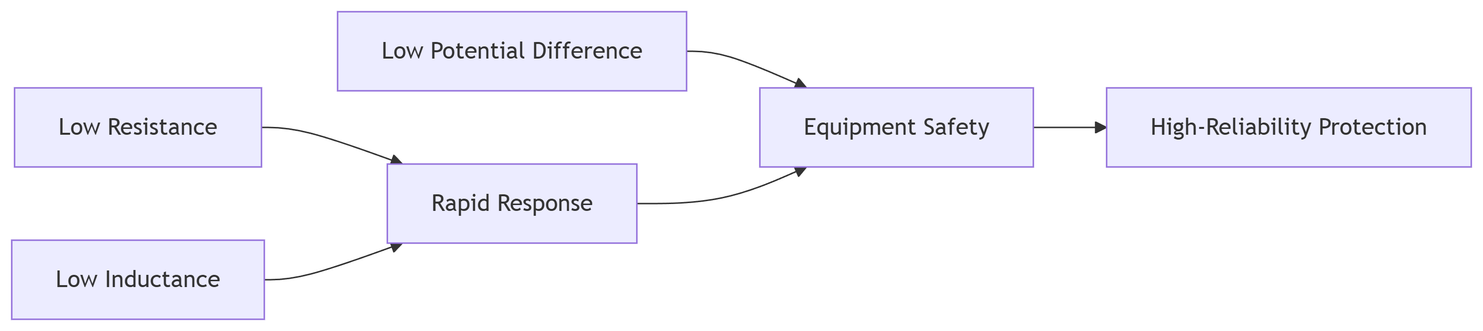
Design Essence: Create lower-impedance paths than equipment, channeling energy to earth.
Ultimate Goal: Achieve “harmless earth dissipation of lightning current”, ensuring 365×24 signal system operation.
IV. Other Critical Design and Construction Considerations
This section serves as the closing loop of lightning protection design, addressing easily overlooked details, construction quality control, and lifecycle management to ensure end-to-end system reliability from design to operation.
① Enhanced Equipotential Bonding (Eliminating Hidden Paths)
Control Cabinet Internal Bonding
| Connection Target | Method | Technical Standard |
|---|---|---|
| Conduit/Raceway Entry | ≥6mm² braid clamped to pipe wall | Independent PEB connection per pipe, R≤0.03Ω |
| SPD Ground Terminal | Dedicated short wire (≤0.3m) | Daisy-chaining prohibited |
| Equipment Rack | Direct copper bar to PEB | Inter-rack jumpers ≥16mm² |
| Signal Cable Shield | Busbar consolidation | ≤20 terminals/bar, anti-loosening crimp |
External Structural Bonding
Pole Flange Bonding:

Adjacent Equipment: When cabinet-pole distance ≤3m, bury 40×4mm galv. steel loop (depth ≥0.8m).
② Lightning-Safe Cable Installation (Suppressing Inductive Coupling)
Layered Segregation
| Cable Type | Layer Position | Segregation Requirement |
|---|---|---|
| 220V AC Power | Bottom of raceway | ≥30cm from signal lines |
| RS485/Ethernet Signals | Middle of raceway | Metal divider if shared raceway |
| Video/Fiber | Top of raceway | Grounded metallic flex conduit at cabinet entries |
Critical Process Controls
- Minimize Loop Area:
- Signal lines: Twisted pairs (pitch ≤15cm)
- Power lines: L-N-PE tightly bundled
- SPD-to-Equipment Distance: ≤5m (add protection if exceeded)
③ Equipment Port Withstand Matching (Design Verification)
| Equipment | Test Standard | Min. Immunity | Max. SPD Up |
|---|---|---|---|
| Controller Mainboard | IEC 61000-4-5 | Level 4 (4kV) | ≤1.2kV |
| Network Switch | IEEE 802.3af | 6kV contact | ≤1.0kV |
| Vehicle Detector | NEMA TS2-2003 | 15kV air discharge | ≤800V |
| LED Driver | IEC 61547 | 2kV CM/1kV DM | ≤600V |
Verification Formula:
SPD Up + (Ground Wire Length × 1kV/m) < Equipment Withstand × 0.8
*Example: Withstand=4kV, SPD Up=1.5kV → Max. ground wire length=1.7m*
④ Corrosion & Mechanical Protection (Ensuring Longevity)
Ground Electrode Corrosion Protection
| Environment | Protection Measure | Service Life |
|---|---|---|
| Normal Soil | Zn≥80μm + asphalt coating | ≥15 years |
| Acidic/Coastal Soil | 304 stainless steel + Mg sacrificial anode | ≥25 years |
| High Chloride Areas | Cu-clad steel (Cu≥0.5mm) + cathodic protection | ≥30 years |
Harness Physical Protection
- Direct Burial:
- Dual-layer: PVC inner + galv. steel outer conduit (wall≥2.5mm)
- Depth: Roadways ≥1.0m, sidewalks ≥0.8m
- Overhead Runs:
- Steel strand support + stainless steel ties (wind load ≥Beaufort 12)
- UV-resistant jacket (≥5,000 hours UV rating)
⑤ Smart Monitoring & Maintenance (Proactive Defense)
Online Monitoring System
[Lightning Counter] → [SPD Degradation Sensor] → [Remote Ground R Test] → [4G] → [Cloud]
                      ↓                             ↓
                Audible/Visual Alarm           Maintenance Ticket
SPD EOL Alert: Real-time leakage current monitoring (>1mA trigger)
Ground Resistance Alert: >10% deviation alarm
Maintenance Protocol
| Task | Frequency | Procedure | Tool |
|---|---|---|---|
| SPD Status Check | Quarterly | Replace if red window/counter increment | IR thermal camera |
| Connection Torque Verify | Annually | Fasteners ≥25N·m, no loose crimps | Digital torque wrench |
| Ground R Retest | Pre-storm | ΔR ≤10% | Clamp ground tester |
| Coating Inspection | Triennially | Zn≥65μm, repair with epoxy | Coating thickness gauge |
⑥ Failure Case Studies & Corrective Actions
- Case 1: Widespread Signal Damage
- Root Cause:
- Missing equipotential bonding (32V potential between cabinet & SPD ground)
- No signal line SPDs (RS485 chips destroyed)
- Solution:
- Install 30×5mm PEB copper bar
- Add TVS arrays (Up≤15V) to all signal lines
- Root Cause:
- Case 2: Ground Grid Corrosion in 3 Years
- Root Cause:
- Flat steel thickness=2.0mm (required ≥4mm)
- Unprotected weld points
- Solution:
- Replace with 40×4mm 304 stainless steel
- Seal welds with brazing + anti-corrosion paste
- Root Cause:
Conclusion: The “Last Mile” of Lightning Protection
“Lightning protection success hinges on details”:
- An ungrounded shield loses 90% effectiveness
- 10cm ground wire adds ≈200V residual voltage
- 0.5mm coating defect reduces electrode life by 5 years
Rigorous implementation of these measures addresses 98% of lightning failures caused by construction flaws, achieving zero-failure lifecycle performance for traffic signal lightning protection systems.
Reach a Verdict
The lightning protection design of traffic signal light harness is the lifeline to ensure the stable operation of urban transportation “nerve veins” in thunderstorms. Through the external direct lightning interception, induced lightning multi-level discharge, low-resistance grounding system construction and refinement of the construction control of the four core strategies, the formation of “interception – channeling – isolation – clamp position” of the three-dimensional protection network. Only rigorous design throughout the selection, installation, maintenance of the whole chain, to ensure that the signal system 365 days without fear of wind and rain, to provide a solid barrier for road safety. Lightning protection is not a one-day effort, need to build every line of defense with systems engineering thinking.
Nenhum comentário para mostrar.


Leave a Comment