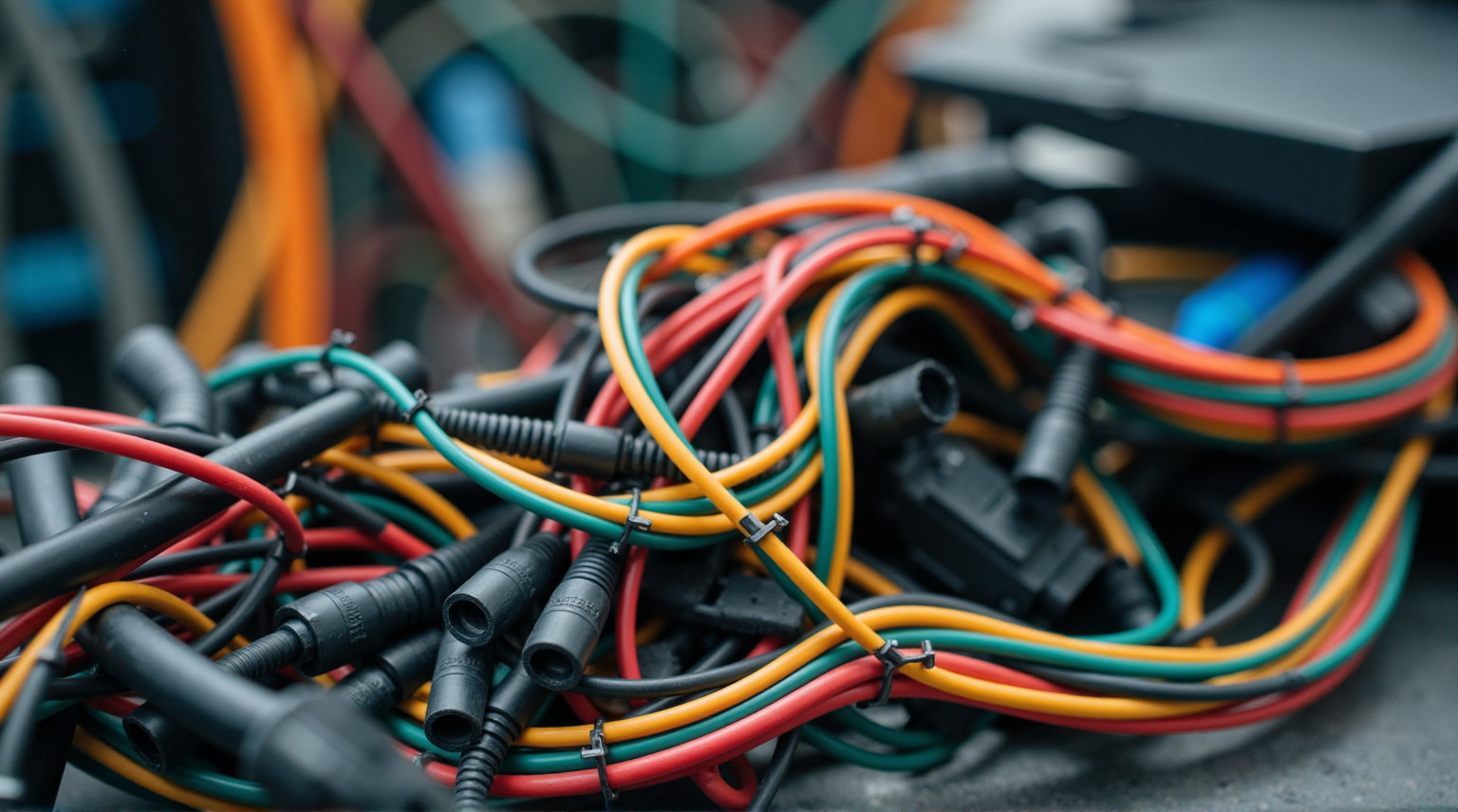
Wire Harness Colors: What Do Different Colors Represent?(CAR)
Lightning strikes pose a critical threat to the stable operation of traffic signal systems. The immense energy generated can readily invade through power and signal wire harnesses, causing equipment damage and traffic paralysis. For lightning protection design of wire harnesses, a <strong>three-pronged integrated protection system</strong> encompassing <strong>external direct-strike protection, induced lightning surge suppression, low-resistance grounding, and precision construction</strong> must be established. This forms a solid foundation for ensuring the safe and reliable operation of urban traffic signals.
!!! Notice (For Reference Only) !!!
This article provides general knowledge about automotive wire color codes. Please note:
▶Not Universal: Variations exist across brands/models – always refer to the vehicle’s service manual.
▶Safety Priority: For high-voltage systems (e.g., orange cables) or airbags, rely on professionals.
▶Compatibility Check: Verify color functions match your vehicle before modifications.
▶Disclaimer: Content is for technical reference only; no liability for operational risks.
▼▼ Power Supply ▼▼
The power supply wiring harness is primarily responsible for providing electrical energy to various vehicle systems. Its color coding is typically used to distinguish between different power types and voltage levels. Below are common power supply wire colors and their functions:
1. Red
● Main Power Positive (+B, Battery Power)
○ Directly connected to the battery positive terminal, providing constant power (not controlled by the ignition switch).
○ Common applications: Main power supply to fuse box, ECU memory power (e.g., anti-theft system, clock).
● ACC Power (Accessory Power)
○ Some models use red (or red with stripes) for circuits energized when the ignition switch is in the ACC position, such as the radio or cigarette lighter.

▲ High-temperature Resistant Ultra-flexible Silicone Wire for Lithium Batteries ▲
2. Yellow
● Continuous Power Circuit
○ Used for devices requiring long-term power supply, such as ECU data storage or BCM backup power.
● Backup Power
○ In some models, it serves as emergency or jumper circuits, e.g., constant power for OBD-II diagnostic ports.
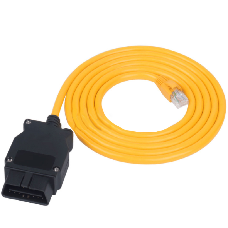
▲ OBD-II Diagnostic Interface Wiring Harness ▲
3. Orange
● Ignition Switch-Controlled Power (IGN, Ignition Power)
○ Energized only when the ignition switch is in ON or START, e.g., fuel pump, instrument cluster, engine control system.
● Safety System Power
○ In some models, it powers safety systems like SRS airbags, ABS, or ESP.
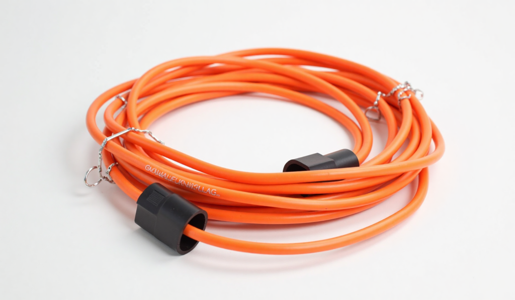
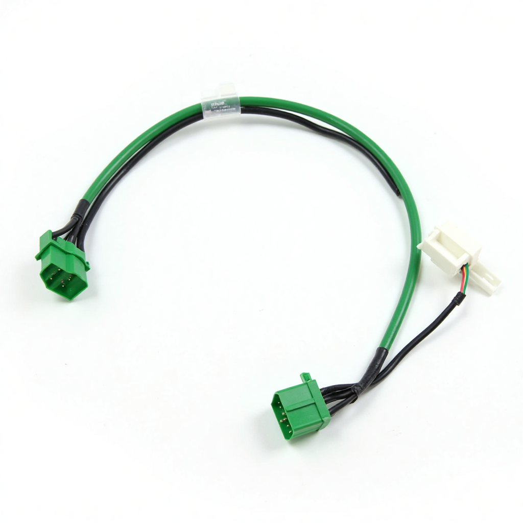
▲ Ignition Switch Control Harness ▲
4. White
● Auxiliary Power (Some Models)
○ May supply low-power devices like interior ambient lighting.
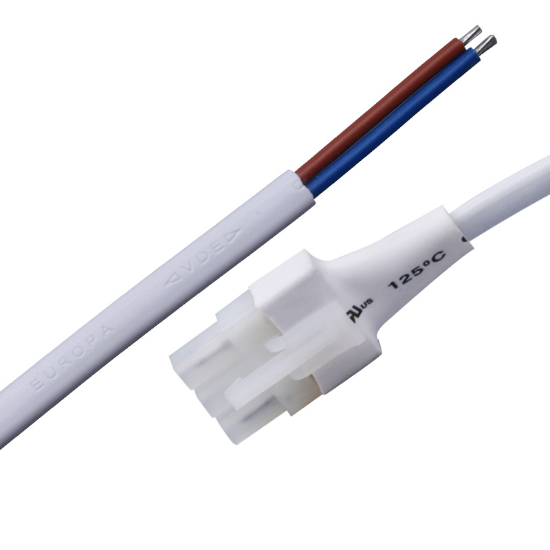
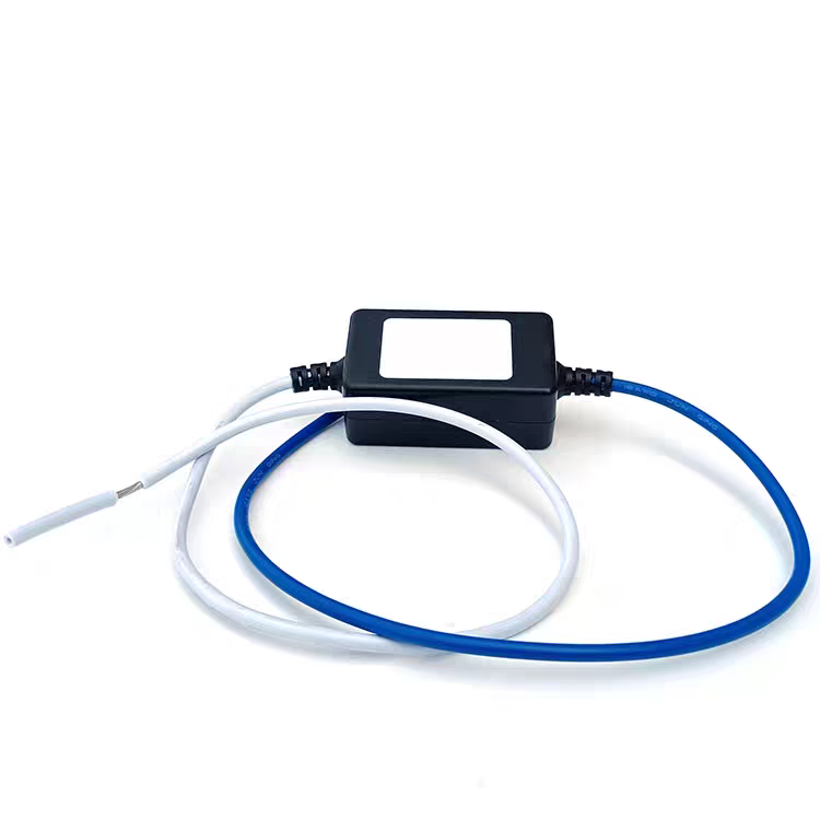
▲ LED Lighting Cable/Wiring ▲
5. Two-Tone Wires (e.g., Red/Black, Red/White)
● Composite Power Circuits
○ Red with black stripes may indicate a branch of the main power (e.g., audio system supply).
○ Red with white stripes may represent ACC power (e.g., cigarette lighter circuit).
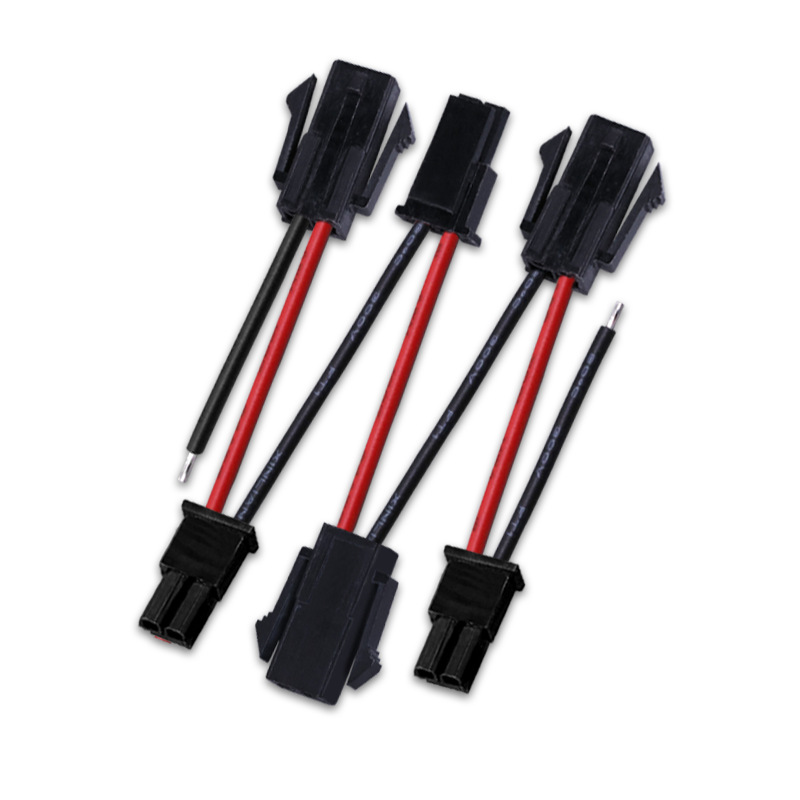
▲ Automotive Audio Wiring Harness ▲
▼ Notes ▼
○ Variations by Manufacturer: For example, American cars often use pink for fuel pump control, while Japanese models may use other colors.
○ High-Voltage Systems (EVs): High-voltage battery cables are typically orange (indicating hazardous voltage, e.g., 300V+) and require professional handling.
○ Verification During Repairs: Color coding is for reference only; always verify with circuit diagrams or a multimeter to avoid errors.
○ The function of the wire harness color may not be the same in each region, please pay attention to identify the function of the wire harness to avoid damage to the car parts.
▼▼ Grounding System ▼▼
The ground wire (GND) forms the return path of an electrical system, directing current back to the power source negative terminal (battery or chassis ground). Different colored ground wires may indicate different grounding types or purposes. Here are the common classifications:
1. Black
● Main Ground Wire:
○ Directly connected to the battery negative terminal or chassis ground point, providing a common return path for all vehicle electrical equipment.
○ Commonly used for grounding major components like ECU (Engine Control Unit), audio systems, and instrument clusters.
● Signal Ground (Sensor Ground):
○ Used for low-current return paths of sensors and control modules to reduce signal interference (e.g., oxygen sensors, throttle position sensors).
○ Some vehicle models use black/white striped wires for dedicated signal grounding.
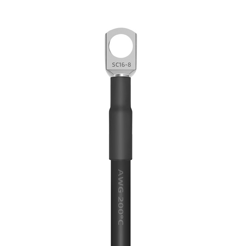
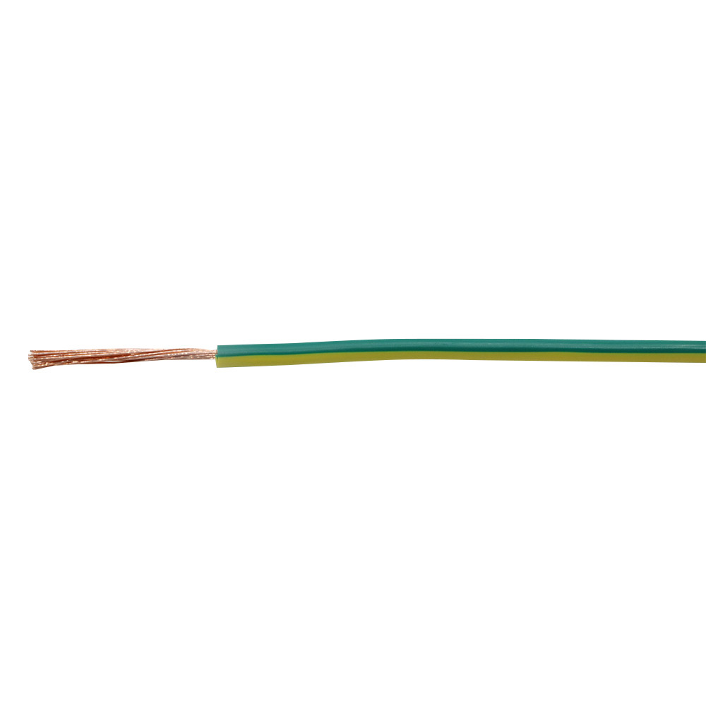
▲ Grounding Cable ▲
2. Brown
● Auxiliary Ground (High-Current Devices):
○ Used for grounding high-power devices like headlights, taillights, and power seats to distinguish from main ground circuits.
○ Some European vehicles (e.g., Volkswagen, Audi) commonly use brown as the standard ground color.
● Chassis Ground:
○ Directly attached to the vehicle’s metal frame to ensure low-impedance return paths (e.g., audio amplifiers, trunk lighting).
3. Black/White Stripe
● Shield Ground:
○ Used for wiring harnesses that shield against high-frequency interference (e.g., knock sensors, crankshaft position sensors), with outer braided layers grounded to resist electromagnetic interference (EMI).
● Diagnostic Interface Ground:
○ OBD-II diagnostic interface ground wires may use black/white stripes to ensure signal stability.

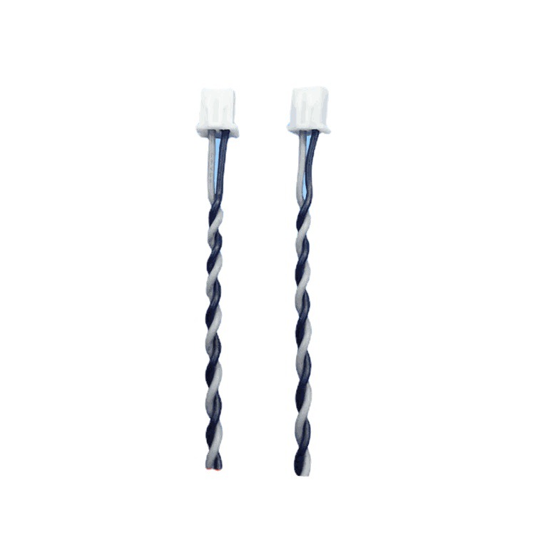
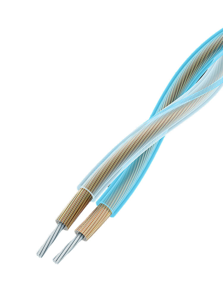
▲ Silver Plated Shielded Signal Cable ▲
4. Green/Black Stripe
● Special Equipment Ground:
○ Used in some Japanese vehicles for independent grounding of ABS modules and airbag systems to prevent interference from sharing ground with other circuits.
▼ Notes ▼
○ Colors Are Not Absolute: Different manufacturers may use custom colors.
○ Effects of Poor Grounding : Can cause dim lights, ECU false trouble codes, abnormal sensor signals, etc.
○ Verification Required: During repairs, use a multimeter (resistance mode) to confirm if the ground wire connects properly to the chassis or battery negative.
○ The function of the wire harness color may not be the same in each region, please pay attention to identify the function of the wire harness to avoid damage to the car parts.
▼▼ Lighting & Signals ▼▼
In automotive electrical systems, the color coding of lighting and signal wiring harnesses is primarily used to distinguish circuits for lights, turn signals, brake lights, etc. Different colored wires represent different functions, facilitating maintenance and troubleshooting.
1. Green
● Functions:
○ Right Turn Signal: In some models (especially Japanese cars), green wires control the right turn signal or right side of hazard warning lights.
○ Brake Light Signal: Some vehicles use green wires to connect the brake switch to taillights.
○ Sensor Signals: Output wires for speed sensors or ABS wheel speed sensors may be green.
● Typical Applications:
○ Turn signal relay → right turn light, brake light switch → taillight.
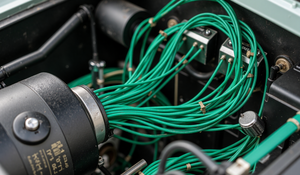
▲ Turn Signal Wiring Harness ▲
2. Blue
● Functions:
○ Left Turn Signal: Typically used for left turn signals or left side of hazard lights.
○ High Beam Control: Connects the combination switch to high beam relay or directly controls high beams.
○ Fog Light Control: Some models use blue wires for front/rear fog lights.
● Typical Applications:
○ Turn signal switch → left turn light, headlight switch → high beam relay.
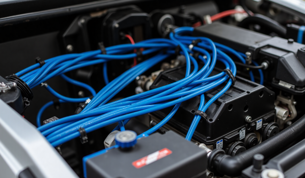
▲ Turn Signal Wiring Harness ▲
3. White
● Functions:
○ Low Beam: Used for headlight low beam circuits, connecting headlight switch or relay to low beams.
○ Reverse Light: Connects reverse switch to reverse lights in some models.
○ License Plate Light: Some vehicles use white wires for license plate illumination.
● Typical Applications:
○ Headlight switch → low beam, reverse switch → reverse light.
▲ Headlight Low Beam Wiring Harness ▲
4. Yellow/Amber
● Functions:
○ Universal Turn Signal: If vehicles don’t distinguish left/right turn signals, yellow wires may be used uniformly.
○ Position Lights (Parking Lights): Some models use yellow wires for position lights or daytime running lights (DRL).
● Typical Applications:
○ Turn signal switch → turn lights, light switch → position lights.
5. Red or Red/Black
● Functions:
○ Brake Light Power: Some vehicles use red wires to connect brake switch to taillights.
○ Taillight Power Supply: Certain models use red wires to provide constant power to taillights.
● Functions:
○ Brake switch → brake lights, taillight power wires.
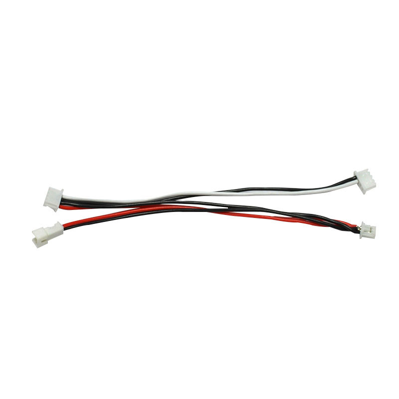
▲ Connection Line ▲
6. Brown
● Functions:
○ Taillight/License Plate Light Ground: Some European cars use brown wires as ground return for lights.
○ Position Light Ground: Ground for position lights or instrument backlighting may use brown.
● Typical Applications:
○ Taillight → chassis ground, license plate light → ground.
7. Two-Tone Wires (e.g., Green/White, Blue/Black)
● Functions:
○ Composite Signal Control: For example, green/white may represent right turn signal + brake light signal.
○ Shielded Signal Wires: Reverse radar or camera harnesses may use two-tone wires to distinguish signals from ground.
● Typical Applications:
○ Advanced lighting systems, ADAS-related wiring.
▼ Notes ▼
○ Variations by manufacturer: For example, German cars often use brown for ground, while Japanese models may use black or green.
○ LED lighting systems: Modern vehicles may use thinner gauges or different color codes – consult service manuals.
○ Modification precautions: When adding lighting equipment, match original wire colors or use relays to prevent overloads.
○ The function of the wire harness color may not be the same in each region, please pay attention to identify the function of the wire harness to avoid damage to the car parts.
▶▶▶Identifying wire colors helps quickly locate lighting/signal system faults, but always verify with circuit diagrams or multimeter testing.◀◀◀
▼▼ Control & Communication ▼▼
Control and communication wiring harnesses are primarily used for transmitting signals from electronic control units (ECUs), data communication, and actuator control. Different colors represent different functions such as sensor signals, bus communication, and relay control.
1. Purple
● Functions: Starting control, high-speed communication
○ Starter signal (ST position): Connects ignition switch to starter relay to control engine starting (common in American vehicles).
○ CAN-H (High-speed CAN bus): Some models use purple for CAN bus high-level signal lines (e.g., German vehicles).
○ Fuel injection control: Some models may use purple for injector control wires.
● Typical Applications:
○ Starter motor control wire, ECU communication line.
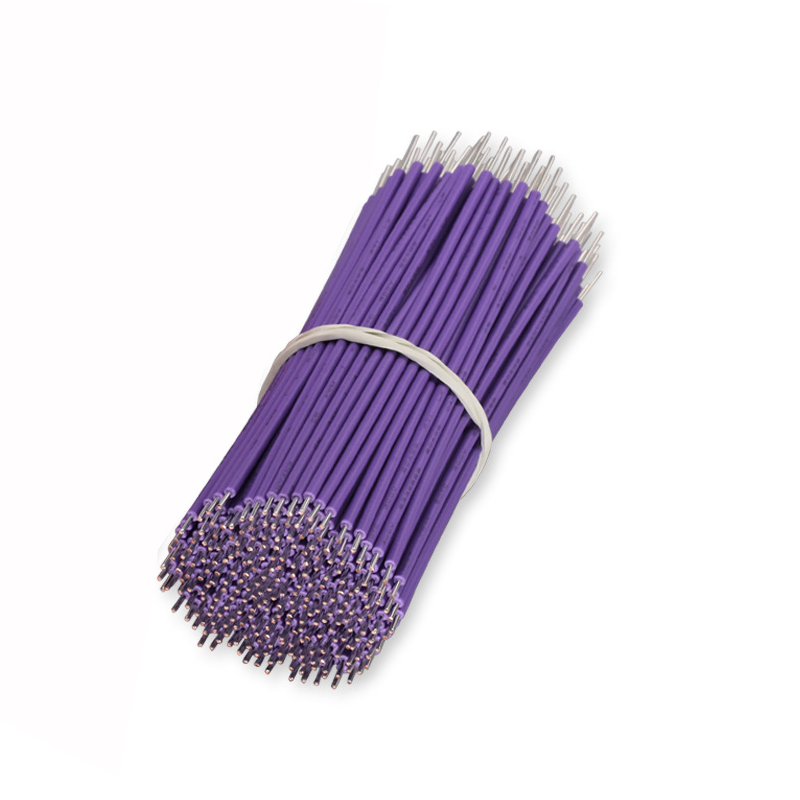
▲ Sensor signal lines ▲
2. Gray
● Functions: Sensor signals, low-speed communication
○ Sensor ground or signal wires: e.g., intake air temperature sensor, throttle position sensor signal return.
○ CAN-L (Low-speed CAN bus): Paired with purple CAN-H for in-vehicle network communication (e.g., OBD-II diagnostic interface).
○ Instrument signals: Some models may use gray for instrument cluster data feedback wires.
● Typical Applications:
○ Oxygen sensor signal wire, CAN bus communication.
3. Pink
● Functions: Fuel system control, ECU commands
○ Fuel pump control wire: Power supply/control signal from ECU or relay to fuel pump (common in Japanese/American vehicles).
○ Injector control: Some models use pink for injector drive signals.
○ Safety system signals: e.g., airbag module trigger signals (some models).
● Typical Applications:
○ Fuel pump relay control wire, ECU output commands.
4. Blue
● Functions: Control signals, low-speed communication
○ Left turn signal control: Signal wire from turn switch to flasher relay (some models).
○ Low-speed network communication: e.g., LIN bus may use blue wires.
○ Auxiliary control signals: e.g., power mirror adjustment, window control.
● Typical Applications:
○ Turn signal control, body module communication.
5. Green
● Functions: Sensor signals, data feedback
○ Vehicle Speed Sensor (VSS): Transmits speed signals to ECU or instrument cluster.
○ ABS wheel speed signals: Some models use green for wheel speed sensor harnesses.
○ ECU feedback signals: e.g., diagnostic trouble code signals (related to OBD interface).
● Typical Applications:
○ Vehicle speed sensor wire, ABS signal wire.
6. Orange/Black Stripe
● Functions: Safety system control
○ SRS airbag deployment circuit: Used for airbag module trigger signals (high-risk, never test randomly).
○ Brake system control: Some models may use this color for ABS hydraulic pump control wires.
● Typical Applications:
○ Airbag wiring harness, ESP control.
▼ Summary ▼
Control and communication wire color coding mainly distinguishes between different signal types and communication protocols, such as:
○ Purple, gray → CAN bus communication
○ Pink, green → ECU control signals
○ Orange/black → Safety systems (never test with power on)
▼ Notes ▼
○ Manufacturers may use custom color schemes – always consult the specific vehicle’s service manual to avoid misdiagnosis!
○ The function of the wire harness color may not be the same in each region, please pay attention to identify the function of the wire harness to avoid damage to the car parts.
▼▼ Special Functions ▼▼
Special function wiring harnesses are typically used for critical systems or specific purposes, with unique color coding to distinguish them from regular circuits.
1. Green with Black Stripe
● Functions: Shielded wire or signal ground
● Applications:
○ Used for sensors requiring high interference resistance, such as knock sensors and crankshaft position sensors.
○ The black stripe typically indicates a shield layer or dedicated ground to prevent electromagnetic interference (EMI).
2. Orange with Black
● Functions: SRS airbag system
● Applications:
○ Specifically for airbag deployment circuits, including airbag modules and impact sensor connections.
○ This color warns technicians to exercise caution, as accidental contact may trigger unintended airbag deployment.
3. Pink
● Functions: Fuel system control
● Applications:
○ Fuel pump relay control wires (from ECU or fuel pump switch).
○ Used for injector signal wires in some models (e.g., American vehicles).
4. Blue with White
● Functions: Automatic transmission control
● Applications:
○ Used for transmission control module (TCM) shift signals or solenoid valve control.
○ Applied to 4WD system components (e.g., transfer case control) in some models.
5. Yellow with Green
● Functions: Hybrid/high-voltage systems (non-standard)
● Applications:
○ Used for low-voltage auxiliary systems (e.g., 12V battery management) in some hybrid/electric vehicles.
○ Note: High-voltage cables (300V+) are typically orange and must be clearly distinguished.
6. Red with Blue
● Functions: ABS or ESP systems
▼ Special Color Notes ▼
○ Two-tone wires: Typically indicate composite functions or special purposes – verify with circuit diagrams.
○ High-voltage warning: New energy vehicle high-voltage harnesses (BEV/PHEV) are usually orange – always power down and verify zero residual voltage before handling.
○ Manufacturer variations: Brands may use custom colors (e.g., BMW uses purple for MOST bus) – consult service manuals.
○ The function of the wire harness color may not be the same in each region, please pay attention to identify the function of the wire harness to avoid damage to the car parts.
▼▼ Industry Standard Variations ▼▼
Different automakers or regions may adopt varying wiring harness color coding standards. While many basic functions (e.g., red=power, black=ground) are common, there are still detailed differences.
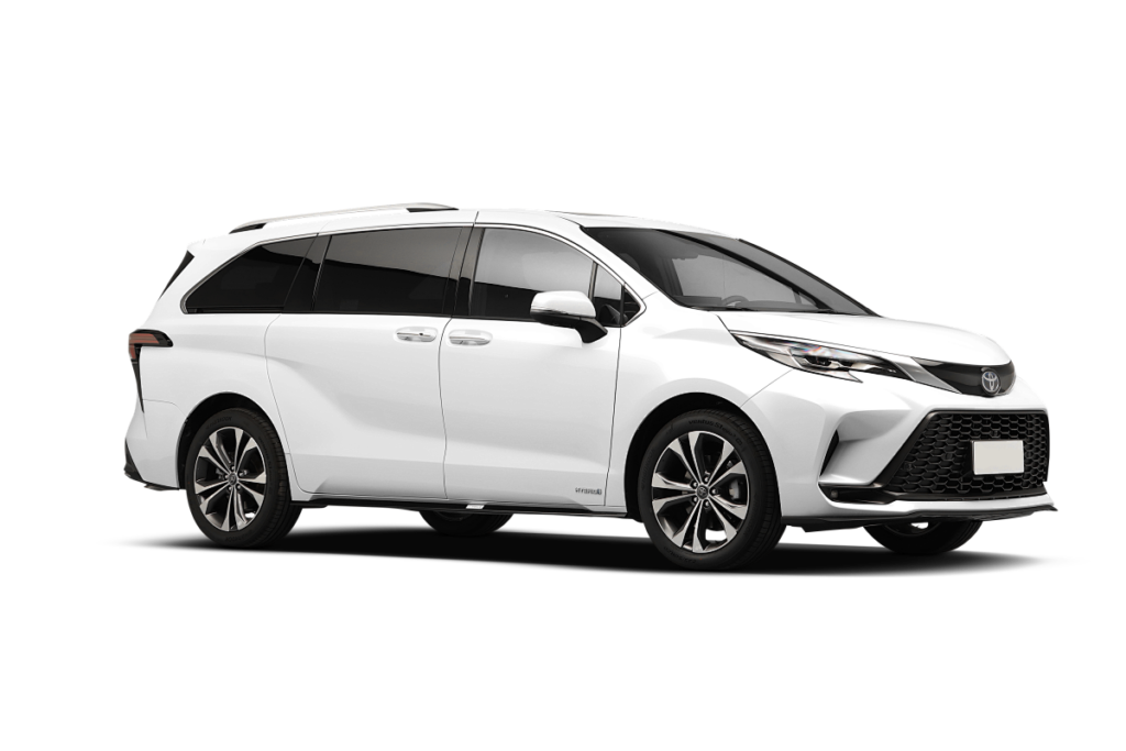
1. Japanese Vehicles (Toyota, Honda, Nissan, etc.)
● Power System:
○ Red: Main power (+B), e.g., direct battery positive connection.
○ White: ACC power (ignition switch controlled).
● Grounding System:
○ Black: Main ground (GND).
● Lighting & Signals:
○ Green: Right turn signal, right brake light.
○ Blue: Left turn signal, left brake light.
○ Yellow: Constant memory power (e.g., ECU storage).
● Lighting & Signals:
○ Pink: Fuel pump control wire.
2. European Vehicles (VW, BMW, Mercedes, etc.)
● Power System:
○ Red: Constant power (direct battery connection).
○ Yellow: Ignition-controlled power (IGN).
● Grounding System:
○ Brown: Main ground (widely used, different from Japanese black).
● Lighting & Signals:
○ Black/White: Turn signals (may not strictly distinguish left/right).
○ Gray: Reverse lights or sensor signals.
● Control Wires:
○ Purple: Starter control (ST position).
○ Green/Black stripe: CAN bus or shielded wires.

3. American Vehicles (Ford, GM, Chrysler, etc.)
● Power System:
○ Orange: Ignition switch power (IGN).
○ Red: Constant power (battery positive).
● Grounding System:
○ Black: Main ground, some models use black/white stripe.
● Lighting & Signals:
○ Blue: High beam control.
○ Green: Right turn signal.
○ Yellow: Left turn signal (reversed in some models).
● Control Wires:
○ Pink: Fuel pump power or control.
○ Purple: Starter relay control (ST position).
4. Chinese Domestic Vehicles (BYD, Geely, Great Wall, etc.)
Generally reference European/Japanese standards, with some custom colors:
○ Red: Main power.
○ Black: Ground.
○ Blue: High beams or left turn signal.
○ Green: Low beams or right turn signal.
○ Two-tone wires (e.g., red/black): May indicate fused power wires.
5. New Energy Vehicles (High-Voltage Harness)
○ Orange: High-voltage battery pack, motor drive lines (DC 300V+).
○ Blue: Low-voltage auxiliary power (12V/24V).
○ Yellow: Charging port signal wires.
▼ Summary ▼
○ Japanese: Green=right turn, Blue=left turn, Black=ground.
○ European: Brown=ground, Purple=starter control..
○ American: Pink=fuel pump, Purple=starter wire.
○ Chinese: Mixed standards, check manuals.
○ NEVs: Orange=high voltage, DO NOT TOUCH!
▼ Note ▼
○ Actual wiring may vary by model year – always consult OEM wiring diagrams!.
○ The function of the wire harness color may not be the same in each region, please pay attention to identify the function of the wire harness to avoid damage to the car parts.
▼▼ Conclusion ▼▼
Wire harness color coding serves as a crucial reference for electrical system maintenance and modifications. However, variations may exist across manufacturers and models. Always verify with circuit diagrams or service manuals during actual operations to prevent misdiagnosis and potential hazards.
For high-voltage systems in new energy vehicles, strict safety protocols must be followed. Orange high-voltage cables should never be handled by untrained personnel.
Accuracy First, Safety Foremost!


Leave a Comment