Regular Inspection of Wiring Harnesses: Best Practices for Fault Prevention
Lightning strikes pose a critical threat to the stable operation of traffic signal systems. The immense energy generated can readily invade through power and signal wire harnesses, causing equipment damage and traffic paralysis. For lightning protection design of wire harnesses, a <strong>three-pronged integrated protection system</strong> encompassing <strong>external direct-strike protection, induced lightning surge suppression, low-resistance grounding, and precision construction</strong> must be established. This forms a solid foundation for ensuring the safe and reliable operation of urban traffic signals.

1. Inspection Frequency and Cycle Planning
1.1 Inspection Cycles for Different Scenarios
Develop differentiated inspection cycles based on wiring harness characteristics in various applications to avoid resource waste or risk oversight caused by “one-size-fits-all” approaches.
• Industrial Equipment Wiring Harnesses
▪ Standard cycle: Conduct comprehensive inspection every 3 months, covering power lines, signal lines and grounding wires.
▪ Harsh environments:
○ High-vibration environments (e.g., stamping machines, conveyors): Increase frequency to monthly inspections, focusing on loose fasteners and insulation wear.
○ High-temperature/humidity environments (e.g., foundries, chemical plants): Monthly inspections with additional focus on aging and oxidation issues.
▪ Critical equipment (e.g., PLC control systems): Visual inspection of connectors every 2 weeks, thorough inspection quarterly.

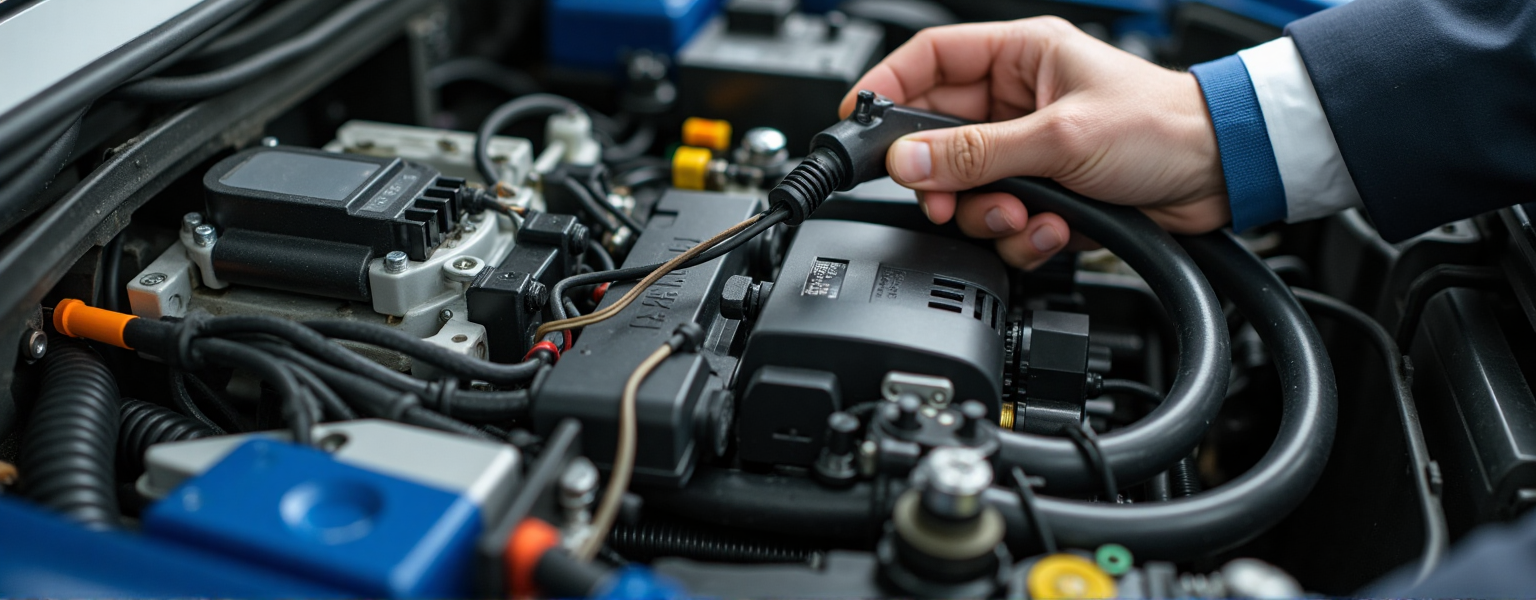
• Automotive Wiring Harnesses
▪ Routine maintenance: Inspect engine compartment and chassis wiring every 10,000 km or 6 months (whichever comes first).
▪ After extreme conditions:
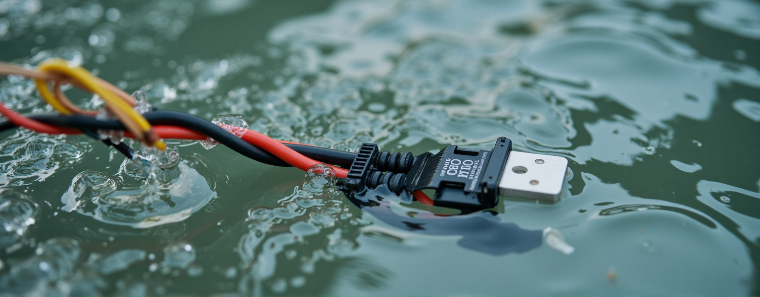
○ Water fording: Immediately check sealing performance, especially waterproofing of ECU and sensor connectors.
○ Extreme cold/heat regions: Seasonal inspections (e.g., cold-weather brittleness before winter, heat damage before summer).
▪ NEV high-voltage wiring: Test insulation resistance every 3 months to prevent leakage risks.
• Electronic Equipment Wiring
▪ Fixed equipment (e.g., server racks): Biannual inspections focusing on thermal aging near cooling fans.
▪ Mobile devices (e.g., portable instruments): Quarterly inspections, with monthly oxidation cleaning for frequently connected interfaces (USB, HDMI).
▪ High-frequency signal lines (e.g., 5G base stations): Test signal attenuation every 2 months using network analyzers.

1.2 Critical Inspection Timings
Beyond regular cycles, immediate inspections are required after specific events to prevent sudden failures:
• After major overhauls or modifications
▪ Verify wiring sequence (e.g., phase consistency) during reassembly to prevent short circuits from incorrect connections.
▪ Evaluate current-carrying capacity after adding loads (e.g., installing motors), upgrade wire gauge if necessary.
• After system upgrades or circuit modifications
▪ Verify shielding integrity after software updates (e.g., check EMI resistance for upgraded CAN buses).
▪ Check for potential interference between wiring and moving parts after layout changes (e.g., harness friction in robotic arm ranges).
• Before restarting after prolonged inactivity
▪ Check for reduced insulation resistance due to humidity (megohmmeter readings should exceed 1MΩ).
▪ Prevent rodent damage using anti-rodent paste or metal sleeves for idle equipment wiring.

1.3 Dynamic Cycle Adjustment Criteria
Inspection cycles should be dynamically optimized based on operational data rather than remaining fixed:
• Environmental factors
▪ Temperature/humidity data: Reduce inspection intervals by 50% if ambient temperature consistently exceeds ratings (e.g., 105°C).
▪ Chemical corrosion monitoring: Add monthly corrosion-resistant coating checks for wiring in acid/alkali environments.
• Load history
▪ Use clamp meters to record peak currents – shorten cycles if sustained overloads (>80% capacity) occur.
▪ Inspect bending points every 2 weeks for fatigue cracks in frequently cycled equipment (e.g., elevator motors).
• Failure rate analysis
▪ Analyze historical failure data to implement “double-frequency inspections” for trouble areas (e.g., loose connectors).

Conclusion:
Scientific inspection planning requires balancing scenario characteristics, environmental risks and real-time data through a tri-level mechanism of “regular cycles + event triggers + dynamic adjustments” to minimize wiring failure probabilities.
For example, an automaker reduced wiring failure rates from 12% to 2.3% while cutting 30% of non-value-added inspection hours through optimized cycle strategies.
2. Inspection Content and Standards
Wiring harness inspections must cover physical condition, electrical performance, and environmental adaptability, with quantifiable criteria established based on industry standards (e.g., ISO 6722 for automotive wiring, IEC 60228 for cables).
2.1 Dynamic Cycle Adjustment Criteria
Assess external damage through visual or assisted tools to identify potential risks.
• Insulation Integrity
▪ Methods:
○ Check for cuts or cracks (especially at bends and fixation points)
○ Use magnifiers or endoscopes for hidden areas (e.g., contact surfaces between engine compartment wiring and brackets)
▪ Criteria:
○ Slight wear (<10% thickness reduction): Mark for monitoring
○ Deep cracks or exposed conductors (>0.5mm): Immediate replacement
• Aging and Deformation
▪ Methods:
○ Tactile evaluation of hardness compared to new harnesses (aged harnesses become stiff/brittle)
○ Thermal imaging to detect insulation deformation from localized overheating (e.g., near exhaust pipes)
▪ Criteria:
○ Yellow discoloration/powdery surfaces (thermal aging signs): Replace
○ Local bulging/shrinkage (thermal deformation): Evaluate conductor impact
• Environmental Damage
▪ Chemical corrosion: Check for oil/acid residue (e.g., near batteries) using pH test strips
▪ Biological damage: Inspect for rodent teeth marks (jagged edges) and protective sleeve integrity

2.2 Connector and Terminal Inspection
Connectors are high-risk areas requiring mechanical strength and electrical contact verification.
• Terminal Condition
▪ Oxidation/Contamination:
○ Clean with ethanol-soaked swabs, check for black oxide (verdigris) or carbon deposits
○ Replace gold-plated terminals with >30% spot oxidation
▪ Deformation:
○ Use insertion/extraction force testers to check pin bending/retraction (e.g., automotive ECU plugs)
○ Verify terminal alignment against OEM drawings (anti-misinsertion feature integrity)

• Mating Performance
▪ Force measurement:
○ Digital torque gauges for insertion/extraction forces (20-50N typical for passenger vehicles)
○ Audible “click” verification of locking mechanisms (e.g., waterproof connectors’ dual-lock)
▪ Durability:
○ Inspect wear on frequently connected interfaces (e.g., USB-C); mandatory replacement after rated cycles (e.g., 10,000 insertions)

• Sealing Verification
▪ Waterproof testing:
○ Air-tightness tests for IP67+ connectors (0.5Bar pressure, <5% leakage in 30s)
○ Inspect rubber gaskets for hardening/cracking/displacement (e.g., door control connectors)
2.3 Electrical Performance Testing
Quantitative evaluation of conductivity and safety using instruments.
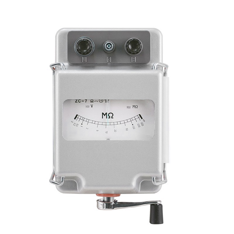
• Insulation Resistance
▪ Method:
○ 500V megohmmeter for conductor-to-conductor/ground measurements (≥60s duration)
○ 1000V megohmmeter for NEV high-voltage wiring (≥500MΩ standard)
▪ Precautions:
○ Disconnect loads before testing; re-test after drying in humid environments
• Continuity and Voltage Drop
▪ Continuity:
○ Multimeter continuity check focusing on weak joints (e.g., relay contacts)
○ Verify each conductor in multi-core harnesses (e.g., CAN bus twisted pairs)
▪ Voltage drop:
○ Measure under full load; troubleshoot if >0.5V drop (12V systems) or >1V (24V systems)
• Signal Integrity
▪ High-frequency lines (Ethernet/coaxial):
○ Network analyzer tests: ≤3dB/100m attenuation, ≤1.5 VSWR
▪ EMI resistance:
○ Oscilloscope waveform analysis; add shielding if PWM jitter >5%
2.4 Mechanical Structure Inspection
Ensure secure fastening to prevent vibration/friction damage.
• Fastener Condition
▪ Check cable ties/clips for breakage/looseness (≤2mm displacement when shaken)
▪ Metal clamps must have rubber sleeves at contact points
• Layout Rationality
▪ Maintain ≥50mm clearance from moving parts (e.g., suspension); add corrugated tubes when needed
▪ Prohibit routing over sharp edges (e.g., sheet metal); inspect existing installations for wear

2.5 Environmental Adaptability Verification
Specialized tests for extreme conditions.
▪ Temperature Resistance
○ High-temperature: 125°C/24h oven test followed by insulation crack inspection
○ Low-temperature: -40°C flexibility test (bend radius ≥4×wire diameter)
▪ Water/Dust Protection
○ Simulated rain (IPX4): Post-spray internal humidity ≤85%RH
○ Dusty environments: Check filter clogging (e.g., construction equipment breather valves)
Conclusion:
Quantifiable metrics (e.g., >1MΩ insulation resistance, 20-50N mating force) and scenario-specific rules (e.g., IP67 waterproof verification) transform subjective experience into actionable standards. A rail transit operator achieved 40% faster troubleshooting and extended critical circuit MTBF from 8,000 to 15,000 hours after implementation.
3. Tools and Methods Optimization
The efficiency and accuracy of wiring harness inspections heavily depend on tool selection and method design. Scientific tool configuration and optimized inspection processes can significantly improve fault detection rates while reducing human errors.
3.1 Selection and Application of Professional Tools
Match tool functionality to inspection objectives to avoid “tool redundancy” or “insufficient capability.”
• Visual Inspection Tools
▪ Endoscope:
○ Application: Inspect hidden damage in confined spaces like engine compartments or equipment interlayers.
○ Key points: Use adjustable lenses (0°-90°), resolution ≥1080P, and secure the harness during inspection to prevent movement.
▪ Infrared Thermal Imager:
○ Function: Locate hotspots (temperature difference >10°C) and identify poor connections or overloaded wiring.
○ Case study: A factory detected abnormal connector temperatures using a thermal imager, preventing a fire and saving 150,000 CNY in repair costs.

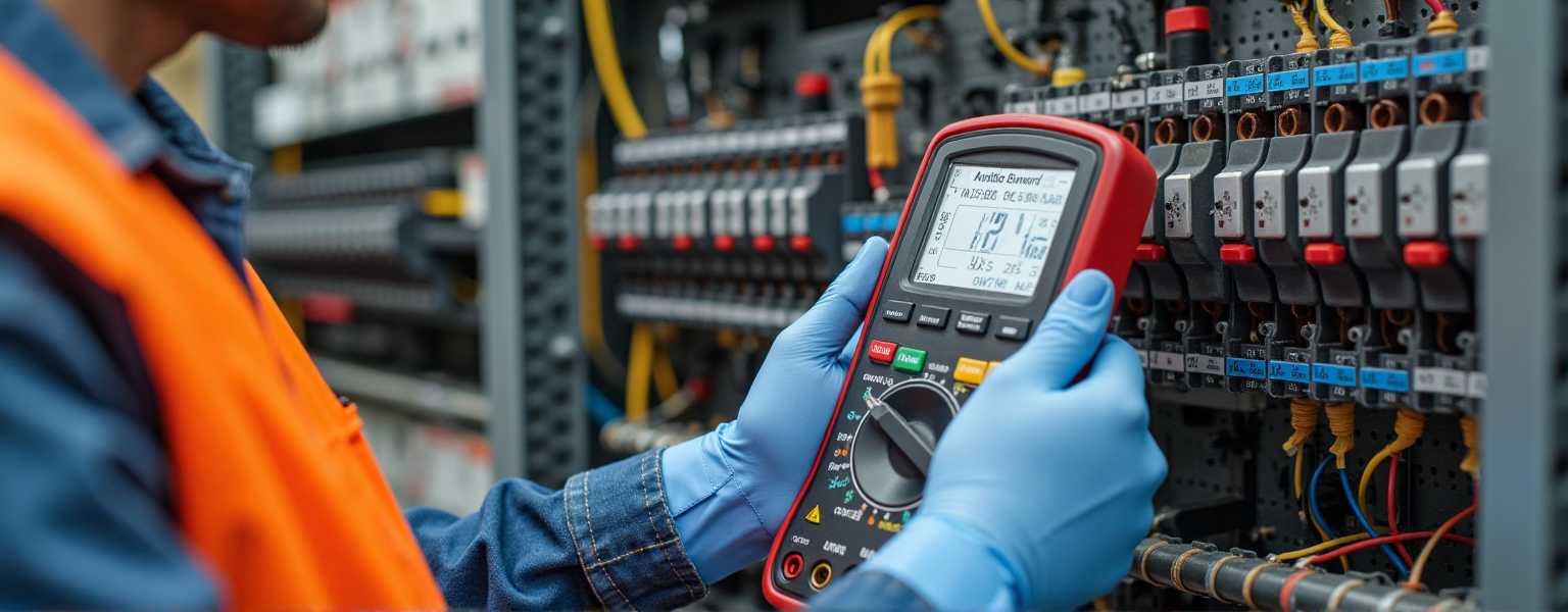
• Electrical Testing Tools
▪ Megohmmeter (Insulation Resistance Tester):
○ Selection: 500V range (±3% accuracy) for standard wiring; 1000V for high-voltage wiring (e.g., EVs).
○ Procedure: Disconnect loads before testing; test duration ≥60 seconds to eliminate capacitance interference.
▪ Wiring Harness Test Bench:
○ Function: Batch-test multi-core harnesses for continuity, shorts, and miswiring (with automated report generation).
○ Efficiency comparison: Manual testing takes 2 hours for 100-core harnesses vs. 10 minutes with test benches, reducing errors by 95%.
• Cleaning and Maintenance Tools
▪ Contact Cleaner:
○ Selection: Use silicone-free, residue-free sprays (e.g., CRC 05103) to avoid conductivity issues.
○ Prohibited actions: Never sand gold-plated terminals; use fiber brushes + ethanol instead.
▪ Protective Materials:
○ High-temperature tape (e.g., 3M 69): Repairs minor wear, withstands -40°C to 150°C.
○ Rodent-proof sleeves: Stainless steel mesh + flame-retardant coating for long-term storage.
3.2 Inspection Process Optimization Methods
The efficiency and accuracy of wiring harness inspections heavily depend on tool selection and method design. Scientific tool configuration and optimized inspection processes can significantly improve fault detection rates while reducing human errors.
• Segmented Testing Method
▪ Power lines: Prioritize main cables (e.g., battery terminals) using clamp meters for real-time current monitoring.
▪ Signal lines:
○ Low-frequency (e.g., sensors): Use multimeters to check voltage stability (<±5% fluctuation).
○ High-frequency (e.g., CAN bus): Use oscilloscopes to detect signal distortion (>10% rise time deviation = abnormal).
▪ Ground loops: Measure resistance (<0.1Ω standard) to identify poor connections/corrosion.
• Standard Operating Procedures (SOP)
▪ Checklist design:
○ Itemized checks by harness ID (e.g., Harness A-01: Insulation ✔, Terminal oxidation ✔).
○ Embedded metrics (e.g., 20-50N mating force; 38N measured = pass).
▪ Photo documentation:
○ Capture overview (location) + close-up (damage) for anomalies. Naming convention: DeviceID_HarnessID_Date.
• Smart Assistive Technologies
▪ AI image analysis:
○ Train models to identify aging (cracks/discoloration), achieving 92% accuracy (automaker data).
▪ RFID tracking:
○ Tag critical harnesses to auto-retrieve inspection history via scanning, reducing manual errors.
3.3 Environmental Adaptability Testing
Design specialized tests for extreme conditions to ensure reliability.
• Vibration Simulation
▪ Tool: Electrodynamic shaker (5-2000Hz, ±2mm amplitude).
▪ Method:
○ Simulate operational vibration for 30 minutes; check for loose fasteners/insulation wear.
○ Automotive harnesses must meet SAE J2380 (equivalent to 250,000km road test).
• Salt Spray Corrosion Test
▪ Equipment: Salt spray chamber (5% NaCl at 35°C, continuous spray).
▪ Criteria:
○ Tin-plated terminals: <5% rust area after 48h.
○ Silver-plated terminals: No visible sulfidation after 72h.
3.4 Data Analysis & Predictive Maintenance
Transform data into preventive strategies, shifting from reactive to proactive maintenance.
• Data Collection & Processing
▪ Tools:
○ Handheld terminals (e.g., Fluke Connect): Auto-upload data to cloud for trend analysis.
○ Health scoring model: Integrate insulation resistance, temperature rise, mating force (0-100 scale).
• Predictive Maintenance Applications
▪ Threshold alerts:
○ Dynamic thresholds (e.g., >10%/month insulation drop) trigger work orders.
▪ Lifespan prediction:
○ Arrhenius model estimates aging at high temps (e.g., 125°C = 1/3 normal lifespan).
Conclusion:
Tool innovation (e.g., AI), process redesign (e.g., segmented testing), and data-driven models can improve efficiency by >50% and detect hidden faults from <60% to 95%.
A heavy industry client reduced downtime by 73% and annual costs by 2.8M CNY after implementation.

4. Emergency Response Plan
Even with strict periodic inspections, wiring harness failures may still occur unexpectedly. A scientific emergency response plan can minimize downtime risks, ensure personnel safety, and buy time for subsequent repairs.
4.1 Temporary Repair Solutions
Implement rapid and effective temporary solutions for different failure types to maintain short-term operation.
• Insulation Damage
▪ Procedure:
○ After power-off, wrap damaged area with insulating tape (e.g., 3M Scotch 35) in spiral pattern with ≥50% overlap.
○ Cover with high-temperature heat shrink tubing (125℃ grade) and evenly heat with hot air gun.
▪ Precautions:
○ Prohibit regular tape (melts easily); mark “TEMPORARY FIX” with date after repair.
○ High-voltage harnesses (>60V) must be shut down immediately – no temporary repairs allowed.
• Poor Terminal Contact
▪ Cleaning method:
○ Spray electronic contact cleaner (e.g., WD-40 Specialist) and clean with nylon brush.
○ Never sand gold-plated terminals; use eraser gently instead.
▪ Pressure enhancement:
○ Adjust pin spring angle with needle-nose pliers (≤0.2mm adjustment) to increase contact pressure.
• Harness Breakage
▪ Quick-connector method:
○ Use insulation-displacement connectors (e.g., Scotchlock) ensuring metal tabs penetrate to conductors.
○ For 0.5-2.5mm² wires; seal with waterproof putty.
▪ Soldering (requires expertise):
○ Use low-temp solder (138℃ melting point) to minimize insulation damage.
4.2 Fault Isolation Strategies
Systematically locate faults to minimize impact scope.
• Sectional Power-Off Method
▪ Steps:
○ Disconnect harness connectors sequentially from load side.
○ Test system functionality after each disconnection until fault clears.
○ Typical application: Locate short circuits in automotive systems by removing relays.
• Signal Injection Method
▪ CAN bus fault location:
○ Measure termination resistance (normal 60Ω) with CAN analyzer after disconnecting nodes.
▪ PLC systems:
○ Inject specific frequency via signal generator; trace attenuation points with oscilloscope.
• Thermal Imaging Assistance
▪ After 30s power-on, scan with thermal imager – sudden temperature rise (>15℃ ΔT) indicates fault location.
4.3 Safety Protocols
Emergency handling must follow safety rules to prevent secondary accidents.
• High-Voltage System Handling
▪ For EV high-voltage harnesses (>300V), first disconnect service plug and wait ≥5 minutes for discharge.
▪ Use CAT III insulated tools and 1000V/Class 0 insulated gloves.
• Flammable Environment Handling
▪ For shorts in oily areas, use CO₂ extinguishers first – never water/foam types.
▪ Use ATEX-certified explosion-proof flashlights to prevent ignition.

4.4 Post-Incident Analysis & Corrective Actions
Implement systematic corrections within 48 hours after temporary repairs to eliminate risks.
• Root Cause Analysis (RCA)
▪ 5Why analysis example:
○ Symptom: Harness melting
→ Why? Current overload
→ Why? Fuse didn’t blow
→ Why? Copper wire replaced fuse
→ Action: Install proper fuses; train against violations.
• Corrective Measures
▪ Material upgrade: Use silicone wires (>50,000 bend cycles) at flex points.
▪ Design improvements:
○ Increase wire gauge (e.g., 1.5→2.5mm²) for overload protection
○ Implement redundant parallel designs for critical circuits.
4.5 Emergency Supplies Checklist
Maintaining these supplies can reduce emergency response time by >30%
| Category | Essential Items | Specifications |
| Insulation | High-voltage insulating tape | Rated ≥600V, 105℃ resistant |
| Connectors | Waterproof splice connectors | IP67, 0.5-4mm² compatible |
| Testing Tools | Non-contact voltage tester | 12-1000V detection range |
| PPE | Arc-rated face shield | ASTM F2178 compliant |
Conclusion:
Scientific emergency plans can reduce average repair time from 4.2 to 1.5 hours (automaker field data).
The three-phase “Temporary Repair → Safe Isolation → Root Cause Correction” process enables both rapid recovery and continuous improvement.
Conduct quarterly drills (e.g., simulated HV harness shorts) to validate plan effectiveness.

Concluding Remarks:
As the core component of modern electrical systems, wiring harness reliability directly impacts equipment safety and operational efficiency. By establishing a scientific periodic inspection system – encompassing precise cycle planning, rigorous testing standards, advanced tool methodologies, and comprehensive emergency protocols – enterprises can systematically reduce failure risks and extend equipment service life.
Practical evidence demonstrates that adopting the preventive maintenance strategies outlined in this document can not only reduce wiring harness failure rates by over 60%, but also significantly improve operational efficiency while achieving substantial cost savings. We recommend enterprises customize these best practices according to their specific working conditions and continuously optimize inspection protocols.
Let standardized wiring harness maintenance become the robust safeguard ensuring production stability.
Görüntülenecek bir yorum yok.

Yorum bırakın