UL94 Flame Retardant Rating Comparison Table
Table of contents
1. HB (Horizontal Burning Test)
Definition and Rating Classification
HB (Horizontal Burning) is the lowest flame retardant rating in the UL94 standard, suitable for scenarios with minimal fire safety requirements. Materials with this rating may burn slowly after flame removal but exhibit self-extinguishing properties or controlled burn rates.
Test Conditions
Sample Requirements
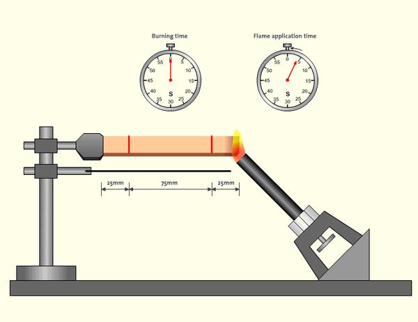
- Dimensions: Typically strip-shaped samples placed horizontally, sized 125mm×13mm×thickness (thickness range: 1.6mm–12.7mm). Some tests require samples of varying thicknesses for consistency verification.
- Preconditioning:
- Stored for at least 48 hours at 23±2℃, 50±5% humidity;
- Some tests require additional aging at 70℃ for 7 days, followed by 4 hours of cooling.
Flame Parameters
- A 20mm blue flame applied at a 45° angle to the sample’s free end;
- Flame Application Time: 30 seconds (terminated early if the flame front does not reach the 25mm mark).
Marking and Timing
- 25mm and 100mm reference lines are marked on the sample to record burn time between these points (or the distance at which burning stops).
Evaluation Criteria
HB rating is determined based on burn rate and self-extinguishing behavior, categorized as follows:
Burn Rate Limits:
- Thickness 3–13mm: Burn rate ≤40mm/min (HB40 grade);
- Thickness <3mm: Burn rate ≤75mm/min (HB75 grade).
Self-Extinguishing Condition:
- If flames extinguish before reaching the 100mm mark, the material qualifies as HB regardless of thickness.
Test Procedure
- Horizontally fix the sample on a stand and apply flame to the free end for 30 seconds before removal;
- Record the time for the flame front to travel from 25mm to 100mm and calculate burn rate (Formula: V=60×burn distance/time);
- Observe whether dripping occurs and if it ignites cotton beneath (HB allows dripping, but HF-1/HF-2 grades impose stricter requirements).
Application Scenarios
- Low-risk applications: Appliance casings, packaging materials, non-critical electronic components;
- Foam materials: HBF, HF-1, and HF-2 rated foams must pass horizontal burning tests, with HF-1 prohibiting dripping and HF-2 allowing controlled dripping.
Key Considerations
- Thickness specification: UL94 ratings must include material thickness (e.g., “UL94 HB@3mm”). Standalone ratings are invalid;
- Test differences: Horizontal burning (HB) is less stringent than vertical burning (V-series), with the latter simulating more realistic fire spread for high-safety applications.
This testing and classification system establishes a quantitative baseline for material flame retardancy. However, HB-rated materials offer significantly lower fire resistance compared to higher grades like V-0 or 5VA, necessitating careful selection based on actual use cases.
2. V-0 (Vertical Burning Test)
Definition and Rating Classification
V-0 (Vertical Burning Class 0) is the highest vertical flame retardant rating in the UL94 standard, requiring materials to self-extinguish rapidly (within 10 seconds) after flame removal without producing flaming drips that could ignite other materials. This rating is suitable for applications with extremely high fire safety requirements, such as core components of electronic devices and critical automotive parts.
Test Conditions
Sample Requirements
- Dimensions: Vertically suspended strip-shaped samples sized 125mm×13mm×thickness (typically 1.6mm-12.7mm thick).
- Preconditioning:
- Standard conditioning: At least 48 hours at 23±2℃, 50±5% humidity;
- High-temperature aging: Another set of samples must be placed in a 70℃ oven for 7 days, then cooled to room temperature (to prevent material degradation from moisture absorption or high temperatures affecting test results).
Flame Parameters
- A 20mm blue flame (using methane gas at 105ml/min flow rate);
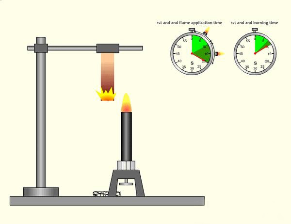
- Flame Application Method: Applied vertically to the sample’s lower end for 10 seconds each time, twice total (if ignition fails on first attempt, replace sample and retest).
Test Environment
- Samples are vertically suspended in a sealed test chamber with absorbent cotton placed 12 inches (300mm) below to detect whether drips ignite the cotton.
Evaluation Criteria
V-0 rating requires meeting all the following conditions simultaneously:
Afterflame Time:
- Single afterflame time ≤10 seconds (must be satisfied for each of the two flame applications);
- Total afterflame time (sum of two afterflames) ≤50 seconds.
Drip Restrictions:
- No dripping that ignites the cotton below (drips may carry flames but must not ignite the cotton).
Sample Integrity:
- Samples must not be completely consumed by burning, and the flame front must not reach the clamping end (i.e., must not burn to the fixture).
Evaluation Criteria
Sample Integrity:
- Vertically fix the sample on a stand and apply flame to the lower end for 10 seconds before removal;
- Record afterflame time (duration of continued burning after flame removal);
- After flames extinguish, immediately reapply flame for 10 seconds and record afterflame time again;
- Check whether the sample burns to the fixture and observe if drips ignite the cotton.
Application Scenarios
- High-safety electronic devices: Power adapter housings, PCB substrates, battery separator plates;
- Automotive industry: Wire harness protectors, internal components of charging stations;
- Industrial equipment: Motor insulation components, high-voltage switch housings;
- Medical devices: Precision instrument housings requiring strict fire certifications.
Key Advantages and Limitations
| Advantages | Limitations |
|---|---|
| Rapid self-extinguishing, prevents fire spread | Higher material costs (e.g., halogen/phosphorus-based flame retardants) |
| No risk of drip ignition | May affect mechanical properties (e.g., increased brittleness) |
| Complies with stringent safety certifications (e.g., IEC) | Requires strict thickness labeling (e.g., “UL94 V-0@1.5mm“) |
Important Notes
- Thickness Sensitivity: V-0 pass rates directly correlate with material thickness. For example, a material may achieve V-0 at 1.6mm thickness but downgrade to V-2 when reduced to 0.8mm.
- Flame Retardant Types:
- Halogen-based retardants (e.g., bromides) easily pass V-0 but may release toxic gases;
- Halogen-free retardants (e.g., aluminum hydroxide, phosphorus-nitrogen) are more eco-friendly but require optimized formulations.
- Test vs. Real-world Risks: Lab tests simulate open flames, but actual fires require additional evaluation of factors like high temperatures and smoke.
Comparison with Other Ratings
| Rating | Afterflame Time (Single) | Drip Ignition of Cotton | Applicable Thickness Range |
|---|---|---|---|
| V-0 | ≤10 seconds | Not allowed | Wide range |
| V-1 | ≤30 seconds | Not allowed | Medium-thick materials |
| V-2 | ≤30 seconds | Allowed | Thin materials |
V-0 is recognized as the “gold standard” in the electronics industry. Its stringent test requirements ensure material safety under extreme conditions, but material selection should consider specific applications and cost-effectiveness.
3. V-1 (Vertical Burning Test)
Definition and Rating Classification
V-1 (Vertical Burning Class 1) is a moderate vertical flame retardant rating in the UL94 standard, requiring materials to self-extinguish after flame removal but allowing longer afterflame time (≤30 seconds per application) compared to V-0. This rating is suitable for medium-to-high safety scenarios requiring a balance between fire performance and cost, such as electronic device housings and internal components of household appliances.
Test Conditions
Test Conditions
- Sample Requirements
- Dimensions: Vertically suspended strip-shaped samples sized 125mm×13mm×thickness (typically 1.6mm-12.7mm thick).
- Preconditioning:
- Standard conditioning: At least 48 hours at 23±2℃, 50±5% humidity;
- High-temperature aging: Another set of samples must be aged in a 70℃ oven for 7 days, then cooled to room temperature before testing.
Flame Parameters
- Flame height: 20mm (methane gas at 105ml/min flow rate);
- Flame application method: Applied vertically to the sample’s lower end for 10 seconds each time, twice total (if ignition fails on first attempt, replace sample).
Test Environment
- Absorbent cotton placed 300mm below samples to detect whether drips ignite the cotton.
Evaluation Criteria
V-1 rating requires meeting all the following conditions simultaneously:
- Afterflame Time:
- Single afterflame time ≤30 seconds (must be satisfied for both flame applications);
- Total afterflame time (sum of two afterflames) ≤250 seconds.
- Drip Restrictions:
- No dripping that ignites the cotton (same as V-0 but with more lenient afterflame time).
- Sample Integrity:
- Samples must not be completely consumed by burning, and the flame front must not reach the clamping end.
Test Procedure
- Vertically fix the sample and apply flame to the lower end for 10 seconds before removal;
- Record afterflame time (duration of continued burning after flame removal);
- After flames extinguish, reapply flame for 10 seconds and record second afterflame time;
- Check whether drips ignite the cotton and confirm the sample doesn’t burn to the fixture.
Application Scenarios
- Consumer electronics: Router housings, printer components;
- Household appliances: Rice cooker bases, vacuum cleaner internal frames;
- Low-voltage electrical components: Connectors, socket housings;
- Industrial equipment: Insulation materials for medium-low risk areas.
Key Features and Limitations
| Features | Limitations |
|---|---|
| Better self-extinguishing than V-2, lower cost than V-0 | Relatively long afterflame time (≤30s) |
| No risk of drip ignition | Thickness sensitive (thin materials may downgrade) |
| Suitable for medium fire protection needs | Requires thickness specification (e.g., “V-1@2mm”) |
Important Notes
- Thickness Impact:
- When material thickness decreases, V-1 may downgrade to V-2 (e.g., a material may achieve V-1 at 3mm but only V-2 at 1mm).
- Flame Retardant Selection:
- Phosphorus-based retardants: Environmentally friendly but may prolong afterflame time;
- Nitrogen-based retardants: Require optimized formulations to meet V-1 time limits.
- Test Repeatability:
- If sample fails to ignite on first flame application, replace with new sample and retest.
Comparison with Other Ratings
| Rating | Single Afterflame Time | Total Afterflame Time | Drip Ignition of Cotton | Typical Thickness Range |
|---|---|---|---|---|
| V-0 | ≤10 seconds | ≤50 seconds | Not allowed | 1.6-12.7mm |
| V-1 | ≤30 seconds | ≤250 seconds | Not allowed | 1.0-6mm |
| V-2 | ≤30 seconds | ≤250 seconds | Allowed | <3mm |
Material Selection Recommendations
- Prefer V-1 for:
- Cost-sensitive applications requiring basic fire certifications (e.g., IEC 60707);
- Materials sensitive to flame retardant effects on mechanical properties (V-1 formulations have less impact on flexibility).
- Avoid V-1 for:
- High-density wiring areas (afterflame time may cause chain risks);
- High-temperature or enclosed environments (require higher ratings like V-0 or 5VA).
V-1 rating provides a cost-effective balance between fire performance and cost, making it a widely adopted “value-for-money” flame retardant standard in electronics manufacturing and appliance industries.
4. V-2 (Vertical Burning Test)
Definition and Rating Classification
V-2 (Vertical Burning Class 2) is the lowest flame retardant rating in UL94 vertical burning tests. It allows materials to produce flaming drips that may ignite cotton below after flame removal, but must meet afterflame time limits (≤30 seconds per application). This rating is suitable for applications with minimal fire safety requirements, such as consumer electronics and non-critical components.
Test Conditions
Sample Requirements
- Dimensions: Vertically suspended strip samples measuring 125mm×13mm×thickness (typical thickness ≤3mm).
- Preconditioning:
- Standard conditioning: 48 hours at 23±2°C, 50±5% humidity;
- High-temperature aging: Additional samples aged in 70°C oven for 7 days, then cooled before testing.
Flame Parameters
- Flame height: 20mm (methane gas at 105ml/min flow rate);
- Flame application method: Applied vertically to sample’s lower end for 10 seconds each time, twice total (replace sample if ignition fails first attempt).
Test Environment
- Absorbent cotton placed 300mm below samples to detect ignition by drips.
Evaluation Criteria
V-2 rating must meet:
- Afterflame Time:
- Single afterflame time ≤30 seconds (both applications);
- Total afterflame time (sum of both) ≤250 seconds.
- Drip Behavior:
- Flaming drips allowed to ignite cotton (key difference from V-0/V-1).
- Sample Integrity:
- Sample must not burn completely; flame front must not reach clamp.
Test Procedure
- Vertically fix sample, apply flame to lower end for 10 seconds then remove;
- Record afterflame time;
- After extinguishing, reapply flame for 10 seconds and record again;
- Observe if drips ignite cotton and confirm sample doesn’t burn to clamp.
Application Scenarios
- Consumer electronics: Phone charger casings, earphone plastic parts;
- Low-risk appliances: Fan blades, humidifier housings;
- Toys & daily items: Plastic toy shells, stationery components;
- Temporary materials: Exhibition decor materials, packaging accessories.
Key Features and Limitations
| Features | Limitations |
|---|---|
| Low cost, easy to pass test | Drips may ignite flammables |
| Suitable for thin materials (<3mm) | Weak fire resistance, not for enclosed spaces |
| Meets basic fire certification | Requires strict thickness marking (e.g. “V-2@1mm”) |
Important Notes
- Thickness Sensitivity:
- Primarily for thin materials (1-2mm); thicker versions may qualify for V-1/V-0.
- Drip Risk Management:
- Avoid use near flammables (e.g. textiles/paper).
- Flame Retardant Selection:
- Typically uses low-cost retardants (e.g. magnesium hydroxide), but may reduce material toughness.
Comparison with Other Ratings
| Rating | Single Afterflame Time | Drip Ignition | Thickness Range | Risk Level |
|---|---|---|---|---|
| V-0 | ≤10s | Not allowed | 1.6-12.7mm | Very High |
| V-1 | ≤30s | Not allowed | 1.0-6mm | Medium |
| V-2 | ≤30s | Allowed | <3mm | Low |
Material Selection Guidelines
- Prefer V-2 when:
- Cost-sensitive with controlled fire risk (e.g. ventilated areas);
- Non-permanent or temporary products (e.g. promotional items).
- Avoid V-2 when:
- High-density electrical equipment (drips may cause shorts);
- High-reliability fields like medical/automotive.
The V-2 rating provides an economical flame retardant solution for low-risk scenarios, but its allowance of flaming drips requires careful consideration of actual usage environments to avoid potential safety hazards.
5. 5VA/5VB (Vertical Burning Test)
Definition and Rating Classification
5VA and 5VB represent the highest flame retardant ratings in the UL94 standard, specifically designed for extreme fire protection requirements. These ratings apply to bulk or thick plate materials (e.g., engineering plastics, composites). Both undergo rigorous multiple flame application tests, with the key difference being:
- 5VA: No burn-through allowed, with afterflame time ≤60 seconds;
- 5VB: Local burn-through permitted, but afterflame time ≤60 seconds.
Typical applications: Aerospace, military equipment, high-voltage electrical components.
Test Conditions
Sample Requirements
- Sample Types:
- Bar samples (testing material’s inherent flame resistance): 125mm×13mm×thickness;
- Plate samples (testing burn-through resistance): 150mm×150mm×thickness (minimum 3mm).
- Preconditioning:
- 48 hours at 23±2℃, 50±5% humidity;
- Additional samples aged in 70℃ oven for 7 days.
Flame Parameters
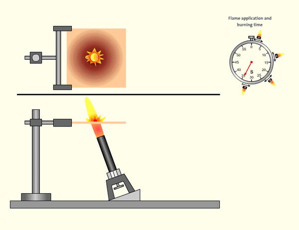
- Flame height: 125mm (5 inches) (methane gas at 965ml/min);
- Flame Application:
- 20° inclined flame applied to sample surface (5 applications of 5 seconds each for bars; 5 applications at plate center for plates).
Evaluation Criteria
| Rating | Single Afterflame Time | Total Afterflame Time (5x) | Burn-Through Limit | Drip Ignition |
|---|---|---|---|---|
| 5VA | ≤60 seconds | ≤300 seconds | Not allowed | Not allowed |
| 5VB | ≤60 seconds | ≤300 seconds | Allowed | Not allowed |
Additional Requirements:
- Samples must not be completely consumed;
- For plates, no holes >30mm diameter allowed in flame application area (5VA only).
Test Procedure
- Bar Sample Testing:
- Apply 20° inclined flame to sample end (5 applications of 5 seconds each);
- Record afterflame times and check for burn-through.
- Plate Sample Testing:
- Apply vertical flame to plate center (5 applications of 5 seconds each);
- Measure burn-through depth/hole size (5VA only).
Application Scenarios
- 5VA:
- Aerospace cabin materials (aircraft seat frames, dashboard components);
- High-voltage electrical equipment (substation insulation boards, charging station housings);
- Military protective gear (ballistic plate covers, ammunition case shells).
- 5VB:
- Industrial machinery high-temperature shields;
- Automotive engine bay heat-resistant parts;
- High-temperature furnace housings (must withstand local burn-through).
Key Advantages and Limitations
| Advantages | Limitations |
|---|---|
| Superior burn-through resistance vs. V-series | High testing costs (multiple flame applications) |
| Suitable for thick materials (≥3mm) | Complex material formulations (require high-efficiency retardants) |
| Complies with stringent international standards (e.g., Airbus AIMS) | May compromise material lightweight properties |
Important Notes
- Thickness and Formulation Optimization:
- Materials <3mm thick typically cannot pass 5VA/5VB tests;
- Commonly use glass-fiber reinforced materials (e.g., PA66+30%GF) or specialty engineering plastics (e.g., PEEK, PEI).
- Flame Retardant Selection:
- Halogen-free systems (e.g., red phosphorus, nitrogen-phosphorus) require precise dosing to avoid mechanical property degradation;
- Ceramifying additives can enhance burn-through resistance (for 5VA).
- Common Failure Reasons:
- Excessive afterflame time (insufficient retardant efficiency);
- Plate sample burn-through (poor material thermal stability).
Comparison with Other Ratings
| Rating | Test Objects | Flame Applications | Burn-Through Limit | Typical Thickness |
|---|---|---|---|---|
| V-0 | Thin materials | 2x (10s each) | Not allowed | 1.6-3mm |
| 5VA | Bulk/plate materials | 5x (5s each) | Not allowed | ≥3mm |
| 5VB | Bulk/plate materials | 5x (5s each) | Allowed | ≥3mm |
Material Selection Guidelines
- Prefer 5VA when:
- Simultaneous flame resistance and structural strength needed (e.g., high-voltage insulation parts);
- Regulations mandate no burn-through risk (e.g., aircraft interior materials).
- Prefer 5VB when:
- Local burn-through acceptable but flame spread must be controlled (e.g., industrial equipment housings);
- Cost-sensitive with thicker materials (higher pass rate than 5VA).
The 5VA/5VB ratings represent UL94’s most stringent fire protection requirements. By withstanding multiple flame impact tests, these materials effectively suppress fire spread in extreme environments, making them the preferred certification standard for high-end industrial and military applications.
6. VTM Series (Thin Film Materials)
Definition and Rating Classification
The VTM (Vertical Thin Material) series is designed for thin film/sheet materials with thickness ≤0.25mm under UL94 standards, comprising three sub-ratings: VTM-0, VTM-1, and VTM-2. This series adapts testing methods (e.g., sample fixation) to accommodate the high flexibility and deformability of thin films, making it widely applicable in packaging, flexible electronics, lightweight components, and other fields.
Test Conditions
Sample Requirements
- Dimensions: Film samples sized 200mm×50mm×thickness (thickness≤0.25mm). Multiple layers may be stacked to achieve total thickness≥0.25mm if single layer is insufficient.
- Preconditioning:
- 48 hours at 23±2℃, 50±5% humidity;
- Additional samples aged in 70℃ oven for 7 days.
Flame Parameters
- Flame height: 20mm (methane gas at 105ml/min);
- Flame Application:
- Vertical application to film’s lower end for 3 seconds (shorter than standard V-series to prevent rapid burn-through).
Test Setup
- Films must be secured in metal frames for vertical suspension without wrinkles;
- Absorbent cotton placed 300mm below to detect drip ignition.
Evaluation Criteria
| Rating | Single Afterflame Time | Total Afterflame Time (2 tests) | Drip Ignition | Burn-Through Limit |
|---|---|---|---|---|
| VTM-0 | ≤10 seconds | ≤30 seconds | Not allowed | No complete burn |
| VTM-1 | ≤30 seconds | ≤250 seconds | Not allowed | Local burn allowed |
| VTM-2 | ≤30 seconds | ≤250 seconds | Allowed | Local burn allowed |
Additional Requirements:
- Samples must not detach from fixture;
- Burn length ≤60% of original length.
Test Procedure
- Securely mount film sample in metal frame for vertical suspension;
- Apply flame to lower end for 3 seconds, then remove and record afterflame time;
- Repeat with another sample (replace if ignition fails initially);
- Check for drip ignition and sample burn extent.
Application Scenarios
- VTM-0:
- High-safety films: Lithium battery separators, flexible PCB substrates;
- Military packaging: Ammunition moisture-proof seals, aircraft protective films.
- VTM-1/VTM-2:
- Consumer electronics: Smartphone screen protectors, wearable device adhesive layers;
- Industrial materials: Lightweight thermal insulation films, temporary anti-corrosion coatings;
- Packaging: Flame-retardant food packaging bags, anti-static films for electronic components.
Key Features and Challenges
| Features | Challenges |
|---|---|
| Adapts to ultra-thin materials (0.01-0.25mm) | Flame retardants may affect flexibility/transparency |
| Testing method prevents excessive burning | Multi-layer stacking may mask single-layer performance |
| Meets lightweight product fire safety needs | Special fixtures required to prevent deformation |
Important Notes
- Thickness and Layer Effects:
- For ultra-thin films (e.g., 0.05mm), stacking to ≥0.25mm may compromise true flame retardancy.
- Flame Retardant Selection:
- Nano retardants (e.g., layered silicates): Minimize transparency impact;
- Coating processes: Apply flame-retardant coatings (e.g., intumescent) to avoid substrate modification.
- Test Accuracy Control:
- Films are airflow-sensitive – tests must be conducted in enclosed chambers;
- Fixtures must prevent edge heat conduction interference.
Comparison with Other Ratings
| Rating | Applicable Thickness | Flame Application Time | Drip Restriction | Typical Applications |
|---|---|---|---|---|
| VTM-0 | ≤0.25mm | 3 sec/application | Not allowed | High-reliability electronic films |
| V-0 | 1.6-12.7mm | 10 sec/application | Not allowed | Electronic component structures |
| 5VA | ≥3mm | 5 sec/application (5x) | Not allowed | Aerospace thick plate materials |
Material Selection Guidelines
- Prefer VTM-0 when:
- UL-certified medical device packaging required (e.g., sterile flame-retardant bags);
- Flexible sensor substrates for high-temperature environments.
- Prefer VTM-2 when:
- Low-cost, short-term packaging needed (e.g., electronic product transport films);
- Non-enclosed environments where drip risk is acceptable.
The VTM series fills UL94’s gap in testing ultra-thin materials, balancing physical properties with flame retardancy requirements through adaptive methods, providing critical safety design standards for lightweight, flexible products.
7. HF Series (Foamed Materials)
Definition and Rating Classification
The HF (Horizontal Foamed Material) series is specifically designed for foamed materials (e.g., polyurethane foam, EPS/EVA foam) under UL94 standards, comprising three sub-ratings: HBF, HF-1, and HF-2. Due to their porous structure which accelerates burning, the HF series evaluates flame retardancy through adapted test methods, making it suitable for packaging, building insulation, automotive interiors and other applications.
Test Conditions
Sample Requirements
- Dimensions: Horizontally placed strip samples sized 150mm×50mm×thickness (typical thickness 6-25mm)
- Preconditioning:
- 48 hours at 23±2℃, 50±5% humidity
- Additional 7-day aging in 70℃ oven for some tests
Flame Parameters
- Flame height: 20mm (methane gas at 105ml/min)
- Flame application: Horizontally applied to sample end for 30 seconds (terminated early if flame front doesn’t reach 25mm mark)
Test Environment
- Samples placed horizontally on wire mesh stand with absorbent cotton underneath to detect drip ignition
Evaluation Criteria
| Rating | Maximum Burn Rate | Drip Ignition | Self-extinguishing Requirement |
|---|---|---|---|
| HBF | ≤40mm/min | Allowed | No specific time limit |
| HF-1 | ≤40mm/min | Not allowed | Flame front extinguishes before 100mm |
| HF-2 | ≤40mm/min | Allowed | Flame front extinguishes before 100mm |
Additional Requirements:
- Post-test sample residual length ≥60% of original
- HF-1/HF-2 must have burn distance ≤100mm
Test Procedure
- Horizontally fix foam sample, apply flame to free end for 30 seconds then remove
- Record time for flame front to travel 25mm-100mm, calculate burn rate (V=60×burn distance/time)
- Observe dripping and cotton ignition
- Verify residual sample length meets requirements
Application Scenarios
- HBF:
- Low-risk packaging: Appliance cushioning foam, logistics filling materials
- Temporary insulation: Exhibition partition foam boards
- HF-1:
- Automotive interiors: Seat foam, headliner padding
- Building fireproofing: Flame-retardant insulation wool, duct liners
- HF-2:
- Furniture materials: Sofa cushions, mattress cores
- Low-cost soundproofing: Studio acoustic foam
Key Features and Challenges
| Features | Challenges |
|---|---|
| Adapts to porous/lightweight foam structures | Flame retardants may reduce elasticity |
| HF-1 provides drip-free safety assurance | High additive loading may increase density |
| Meets construction/automotive fire standards | Foam shrinkage during testing may affect results |
Important Notes
- Density and Porosity Effects:
- High-density foams (≥30kg/m³) more likely to pass HF-1; low-density (<20kg/m³) typically limited to HBF/HF-2
- Flame Retardant Selection:
- Intumescent retardants: Form char layer on surface (suitable for HF-1)
- Liquid retardant impregnation: Penetrates pores uniformly but may affect closed-cell structure
- Test Accuracy Control:
- Secure samples firmly to prevent shrinkage deformation
- Remove flame promptly to avoid sustained burning distorting data
Comparison with Other Ratings
| Rating | Test Orientation | Material Type | Drip Restriction | Typical Applications |
|---|---|---|---|---|
| HB | Horizontal | Regular plastics | Allowed | Low-risk components |
| HBF | Horizontal | Foamed materials | Allowed | Packaging fillers |
| HF-1 | Horizontal | Foamed materials | Not allowed | Automotive/building fireproofing |
| V-0 | Vertical | Dense plastics | Not allowed | High-safety electronics |
Material Selection Guidelines
- Prefer HF-1 when:
- Automotive interiors requiring FMVSS 302 compliance
- Building insulation needing ASTM E84 fire certification
- Prefer HBF when:
- Low-cost cushioning packaging without strict flame retardancy needs
- Short-term use exhibition decor foam
The HF series provides specialized standards for foamed materials through horizontal burning tests, quantifying flame retardancy while balancing safety and material functionality for lightweight, porous material designs.
Summary Table of UL94 Flammability Ratings
| Rating | Test Orientation | Applicable Materials | Key Requirements | Typical Applications |
|---|---|---|---|---|
| HB | Horizontal | General Plastics/Low – Risk Materials | Burn rate≤40 – 75mm/min, dripping allowed | Packaging, appliance casings |
| V – 0 | Vertical | High – Safety Dense Materials | After – flame≤10s, no dripping | Electronic core parts, medical devices |
| V – 1 | Vertical | Medium – Thickness Materials | After – flame≤30s, no dripping | Electronic enclosures, low – voltage electrical parts |
| V – 2 | Vertical | Thin Materials (<3mm) | After – flame≤30s, dripping allowed | Consumer electronics accessories, daily necessities |
| 5VA/5VB | Vertical | Thick Plates/Block Materials | 5 – flame shocks, 5VA no burn – through, 5VB partial allowed | Aerospace, high – voltage equipment |
| VTM Series | Vertical | Films (≤0.25mm) | Short – time flame (3s), divided into VTM – 0/1/2 | Lithium – battery separators, flexible electronics |
| HF Series | Horizontal | Foam Materials (e.g., foams) | HF – 1 no dripping, HBF/HF – 2 dripping allowed | Automotive interiors, building insulation |
Summary Points
Principles for Selecting Ratings:
- Safety First:Choose V – 0 or 5VA for high – risk scenarios (like electronic core parts);
- Cost – Performance Balance:Choose V – 1/V – 2 for moderate requirements, HB/HF – 2 for low – risk cases;
- Material Adaptation:Use VTM for films, HF for foam materials, and 5VA/5VB for thick plates.
Key Differences:
- Vertical Tests (V Series) are stricter than horizontal tests (HB/HF);
- Drip Control distinguishes V – 0/V – 1 from V – 2, and HF – 1 from HBF/HF – 2;
- Thickness Impact:Thin materials are harder to reach high ratings, and thick materials need 5VA/5VB.
Marking Requirements:
- The UL rating must specify the thickness (e.g., V – 0@1.5mm), otherwise it’s invalid.
No comments to show.

Leave a Comment