Wire Gauge and Current Rating Reference Table Classification and Organization
In the field of electrical engineering and electronic equipment design, it is crucial to accurately grasp the matching relationship between wire diameter and current. Wire diameter, i.e. the diameter of the wire, directly determines the current strength that the wire can safely carry. Too small a wire diameter can lead to overheating and safety hazards; too large a wire diameter can lead to material waste and increased costs.
A clear, comprehensive and scientifically categorized wire diameter and current comparison table is like a “navigation map” in the hands of engineers, which can help them quickly select the appropriate wire specifications in complex and changing project requirements. Whether for low-voltage lighting circuits, power equipment lines, or the connection of high-precision electronic components, the comparison table can provide a precise selection basis to ensure the stable operation and efficient performance of the circuit system.
This article will analyze the correspondence between wire diameter and current in various scenarios, and systematically categorize and organize the comparison table according to different materials, uses and other dimensions, to create a practical and convenient reference material for professionals engaged in related work, with a view to improving design efficiency, reducing potential risks, and safeguarding the quality of the project and the life of the equipment.

Table of contents
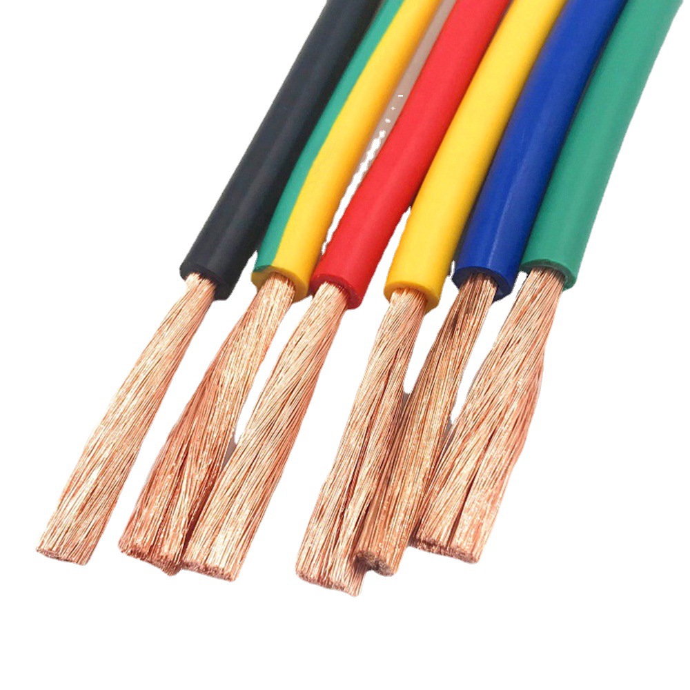
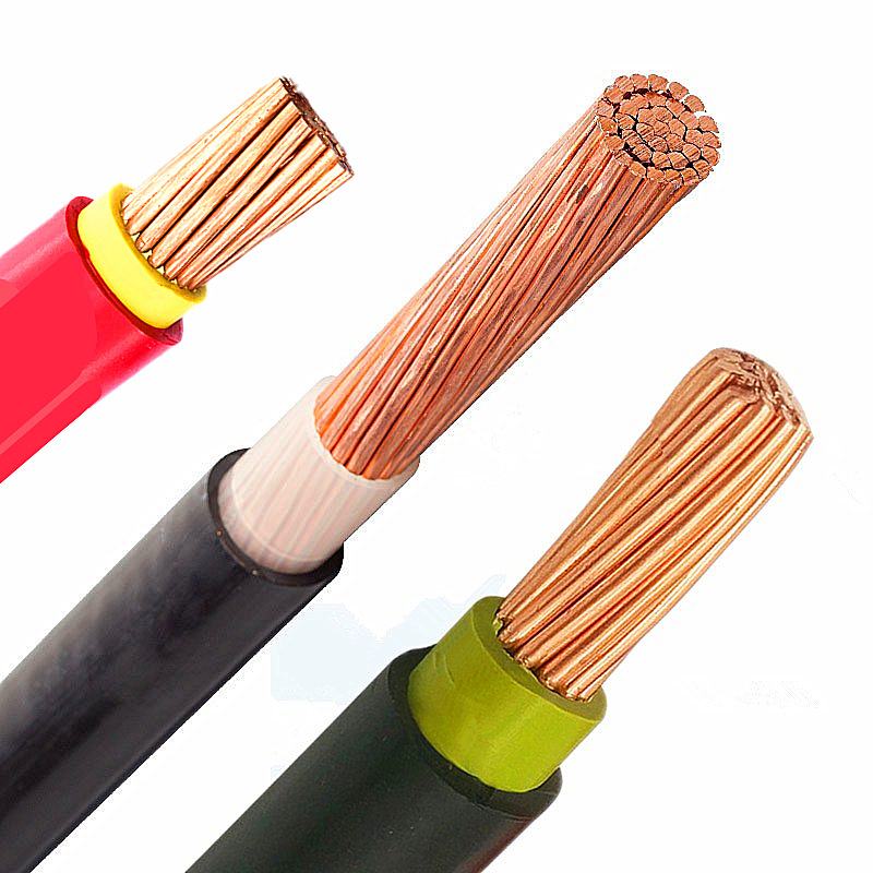
Ⅰ. Copper Conductors (Common)
1. Chinese Standard (GB/T 4706.1)
| Cross-sectional Area (mm²) | Rated Continuous Current (A) | Typical Applications |
|---|---|---|
| 0.5 | 3 | Signal lines, low-power devices |
| 0.75 | 6 | Lighting, small appliances |
| 1.0 | 10 | Branch circuits for sockets |
| 1.5 | 16 | General sockets, lighting |
| 2.5 | 25 | Air conditioners, high-power sockets |
| 4 | 32 | Main circuits, kitchen appliances |
| 6 | 40 | Main supply lines, central AC |
2. IEC Standard (IEC 60287)
- Environmental Temperature & Installation Correction:
- Default conditions: Ambient temperature 30°C, open-air installation.
- Derating required for conduits or high temperatures (e.g., 6mm² copper in conduit: 32A).
3. American Wire Gauge (AWG)
| AWG Number | Cross-sectional Area (mm²) | Current (A) |
|---|---|---|
| 14 | 2.08 | 15 |
| 12 | 3.31 | 20 |
| 10 | 5.26 | 30 |
| 8 | 8.37 | 40 |
Key Notes
- Safety Margin:
- Practical current should not exceed 80% of the rated value.
- Standard Variations:
- Current ratings may vary by region due to insulation materials, parallel conductors, etc.
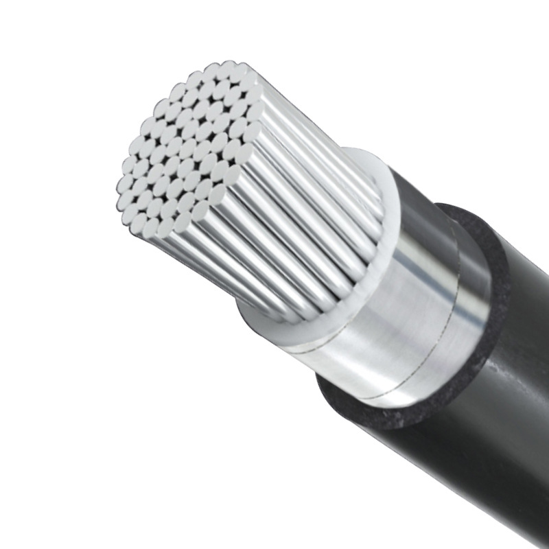
Ⅱ. Aluminum Conductors
※ Note: Aluminum conductors generally require one grade larger cross-sectional area than copper conductors for the same current capacity.
1. Chinese Standard (GB/T 1179)
| Cross-sectional Area (mm²) | Rated Continuous Current (A) | Typical Applications |
|---|---|---|
| 2.5 | 12 | Low-voltage distribution branch circuits |
| 4 | 20 | Power supply for industrial equipment |
| 6 | 25 | Overhead lines, transformer connections |
| 10 | 35 | Main distribution lines |
| 16 | 50 | High-power equipment supply |
2. IEC Standard (IEC 60287)
- Current Rating Adjustments:
- Current capacity of aluminum conductors is approximately 60-70% of equivalent copper conductors.*
- Further derating required for high temperatures or enclosed installations (e.g., 6mm² aluminum at 50°C: 18A).
3. NEC Standard (NFPA 70)
| AWG/kcmil | Cross-sectional Area (mm²) | Current (A) |
|---|---|---|
| 12 | 3.31 | 15 |
| 10 | 5.26 | 25 |
| 8 | 8.37 | 35 |
| 6 | 13.3 | 50 |

4. Key Notes
- Mechanical Strength Limitation:
- Aluminum oxidizes easily; joints require anti-oxidation treatment (e.g., antioxidant paste or bi-metallic lugs).
- Cost-Effective Applications:
- Commonly used in long-distance overhead transmission (lower cost than copper).
- Standard Variations:
- Some regions restrict aluminum conductors in building interiors (e.g., residential circuits in Europe).
Ⅲ. Special Application Scenarios
1. High-Frequency Current (e.g., Switching Power Supplies)
- Skin Effect Impact:
- High-frequency currents concentrate on the conductor surface; use multi-stranded or Litz wire to reduce losses.
- Suggested adjustment: At 100kHz, effective current capacity is ~60-70% of DC.

2. High-Temperature Environments
| Ambient Temperature (°C) | Current Derating Factor | Example (1.5mm² Copper) |
|---|---|---|
| 30 | 1.0 | 16A (Baseline) |
| 40 | 0.91 | 14.5A |
| 50 | 0.82 | 13.1A |
| 60 | 0.71 | 11.4A |
3. DC Systems
- Current Capacity Advantage:
- *DC current capacity is 10-15% higher than AC for the same conductor (no skin/proximity effects).*
- Example: 4mm² copper in DC systems can carry 36A (vs. 32A for AC).

4. Multi-Core Cables
| Number of Cores | Derating Factor | Reason |
|---|---|---|
| 2 | 0.8 | Mutual heating |
| 3-4 | 0.7 | Reduced heat dissipation |
| ≥5 | 0.6 | High density installation |
5. Long-Distance Transmission
- Voltage Drop Limitation:
- Voltage drop should ≤3% (lighting) or 5% (motors) of rated voltage.
- Calculation formula:
Wire diameter (mm²)=2×L×I×ρΔV×V Wire diameter(mm²)=ΔV×V2×L×I×ρ
Where: L=Length (m), I=Current (A), ρ=Resistivity (0.0172 Ω-mm²/m for Cu), ΔV=Allowable Voltage Drop (V), V=System Voltage (V)

Key Notes
- Material Compatibility:
- Use tinned conductors or XLPE insulation in corrosive environments.
- Dynamic Loads:
- Select conductors based on peak current for devices with frequent starts/stops (e.g., motors).
- Standard Hierarchy:
- *Follow manufacturer specifications or industry-specific standards (e.g., CB/T 3492 for marine cables).*
Ⅳ. Key Considerations
1. Safety Margin
※ General Rule: Operating current should not exceed 80% of the rated current to avoid overheating and aging.
Example reference (copper core wire):
| Rated Current (A) | Recommended Max. Operating Current (A) |
|---|---|
| 16 | 12.8 |
| 25 | 20 |
| 32 | 25.6 |

2. Installation Environment
Temperature correction:
For every 5°C increase in ambient temperature, derate current by 3-5% (per IEC 60364-5-52).
Installation Method:
| Installation Type | Derating Factor |
|---|---|
| Open Air | 1.0 |
| In Conduit | 0.8 |
| Buried | 0.7 |
3. Cable Length & Voltage Drop
Pressure drop formula: ΔV(%)=A×V2×L×I×ρ×100
Allowable pressure drop limit:
| Application | Max. Voltage Drop |
|---|---|
| Lighting | 3% |
| Motors | 5% |
4. Material & Standard Compliance
※ Copper and Aluminum Conductor Replacement: Aluminum conductors require 1-2 grades larger than copper (e.g., replace 1.5mm² Cu with 2.5mm² Al).
International differences:
| Region | Typical Standards |
|---|---|
| China | GB/T 3956, GB/T 5013 |
| EU | IEC 60228, EN 50525 |
| USA | NEC 310, UL 83 |
5. Special Load Types
- Motor starting current:
- Select conductors based on 1.5-2.5× rated current (e.g., 10A motor requires 16-25A cable).
- Impulse load:
- Use shielded or twisted-pair cables for high-frequency pulses (e.g., inverters).
Key Notes
- Regular Inspection:
- Inspect aging cables for insulation damage or oxidation (critical for aluminum
- Compatible Accessories:
- Use tinned lugs or bi-metallic connectors for aluminum terminals (prevents galvanic corrosion).
- Legal Compliance:
- Conductor sizing in buildings must comply with local codes (e.g., NEC 210.19 in the USA).
No comments to show.

Leave a Comment