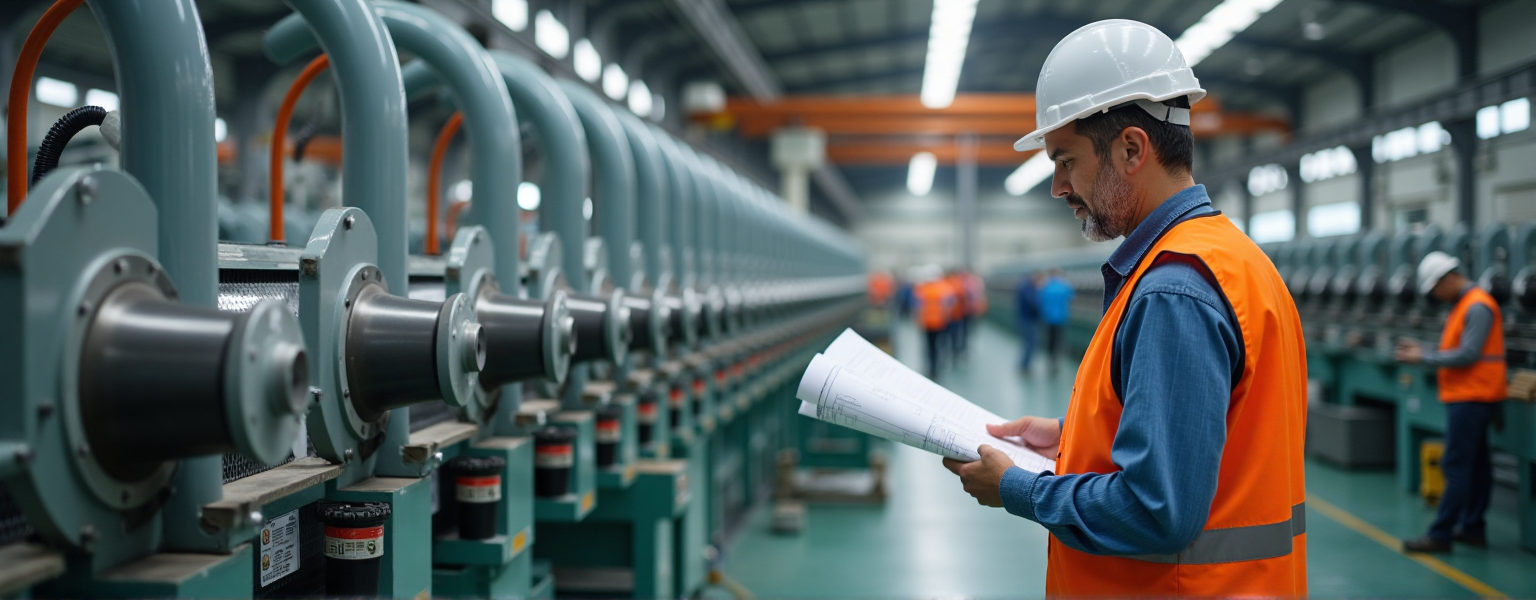
Customized Wiring Harness Design Process: From Requirements to Finished Product
As a professional wiring harness manufacturer, we fully understand the critical importance of customized wiring harnesses in various electronic, automotive, and industrial equipment applications.
A high-quality wiring harness not only ensures stable equipment operation but also enhances the overall system’s safety and durability.
From requirements to finished product, this article provides a detailed breakdown of the entire design process to help you better understand our customized wiring harness solutions.
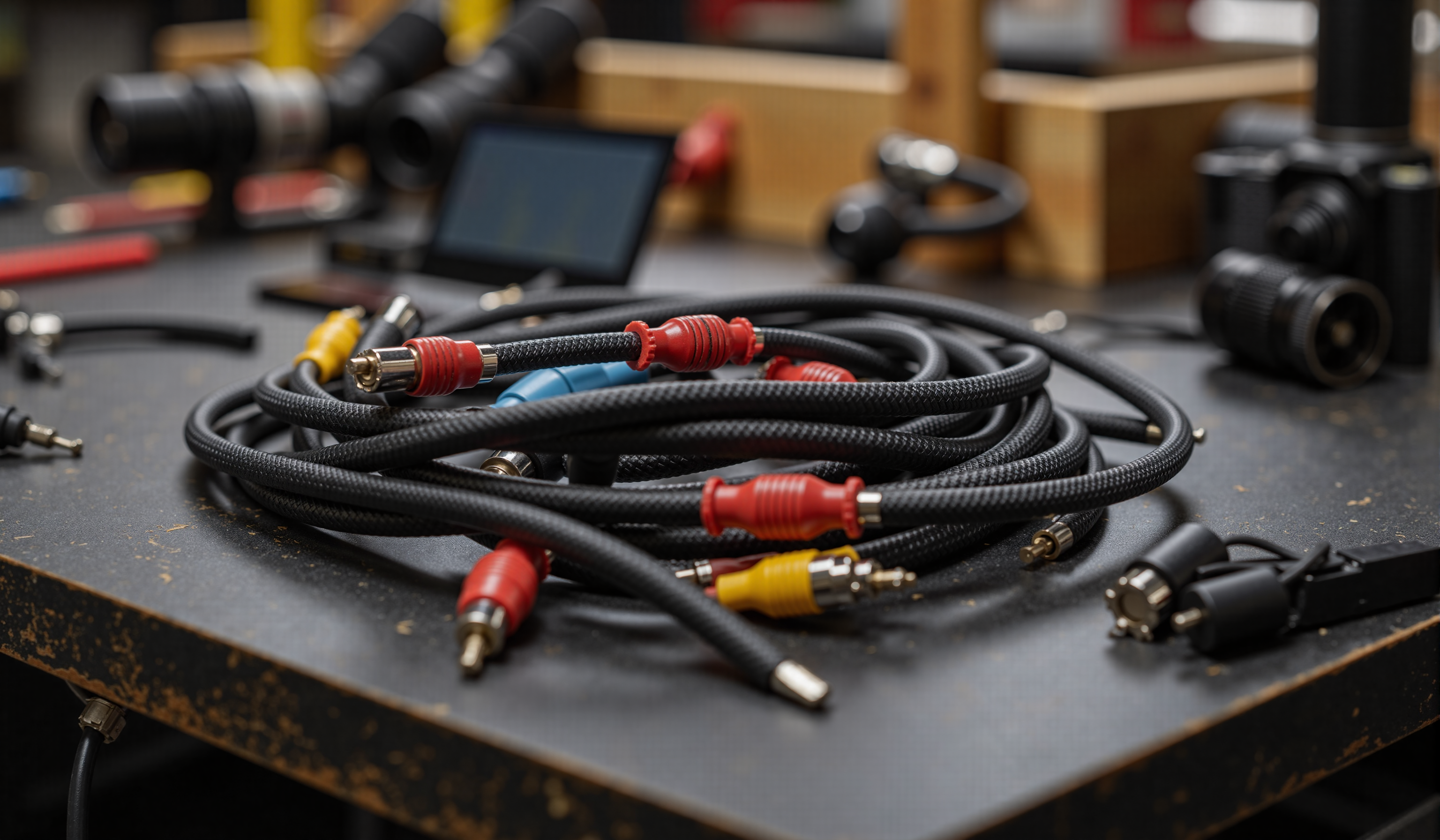
Table of contents
- Customized Wiring Harness Design Process: From Requirements to Finished Product
- ▶ Requirements Analysis and Specifications Confirmation
- 1.1 Customer Requirements Collection
- 1.2 Wiring Harness Functional Definition
- 1.3 Technical Feasibility Assessment
- ▶ Design Phase
- 2.1 Electrical Schematic Design
- 2.2 3D/2D Harness Routing Design
- 2.3 Material Selection
- 2.4 Design Validation (DFM & Simulation)
- 2.5 Deliver Technical Documentation
- ▶ Design Phase
- 3. 1 Rapid Prototyping: From Design to Physical Sample
- 3. 2 Performance Testing: Comprehensive Electrical & Mechanical Validation
- 3. 3 Customer Approval & Design Optimization
- 3. 4 Test Reports & Mass Production Standards
- ▶ Mass Production Preparation
- 4. 1 Process Planning & Optimization
- 4. 2 Quality Control System Implementation
- 4. 3 Supply Chain & Material Management
- 4. 4 Pilot Production (Small-Batch Validation)
- ▶ Mass Production & Delivery
- 5. 1 Large-Scale Production
- 5. 2 Final Inspection & Testing
- 5. 3 Packaging & Logistics
- 5. 4 After-Sales Support & Continuous Improvement
▶ Requirements Analysis and Specifications Confirmation
In the design and manufacturing process of customized wiring harnesses, requirements analysis and specifications confirmation are the most critical first steps.
Only by fully understanding customer requirements can we design wiring harness products that meet application scenarios, deliver stable performance, and are cost-optimized.
1.1 Customer Requirements Collection
We focus on the following aspects:
● Application Scenarios
○ Industry applications: Requirements vary significantly across industries such as automotive, medical, industrial automation, aerospace, and consumer electronics.
○ Installation environment: Indoor, outdoor, underwater, high/low-temperature environments, or environments with strong electromagnetic interference (EMI).
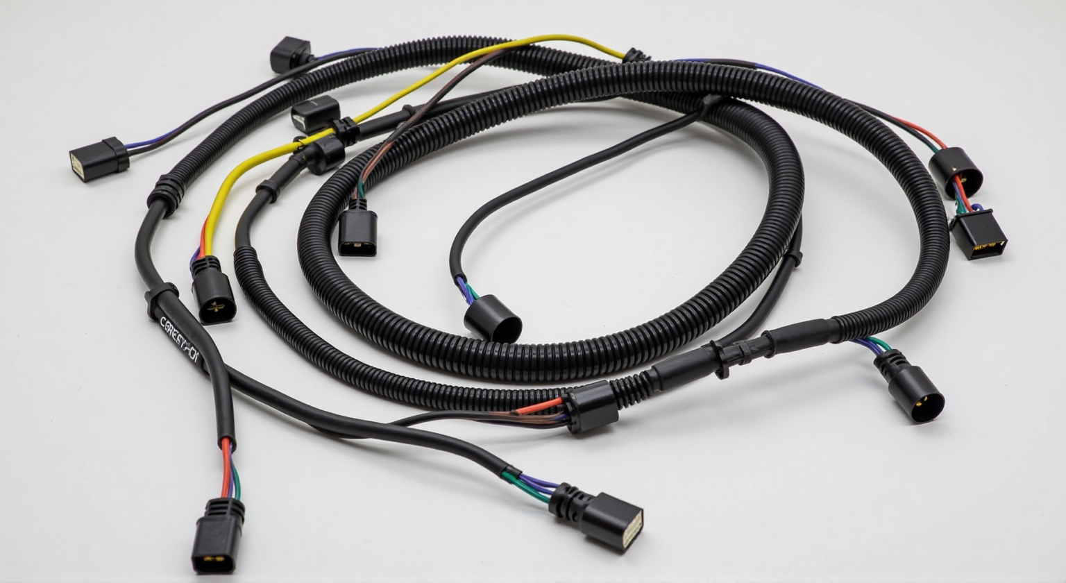
▲ Automotive Wiring Harness ▲
● Electrical Parameters
○ Voltage levels: Low voltage (e.g., 12V/24V), medium voltage (e.g., 48V), or high voltage (e.g., 400V+ for electric vehicles).
○ Current load: Select appropriate wire gauges based on current requirements.
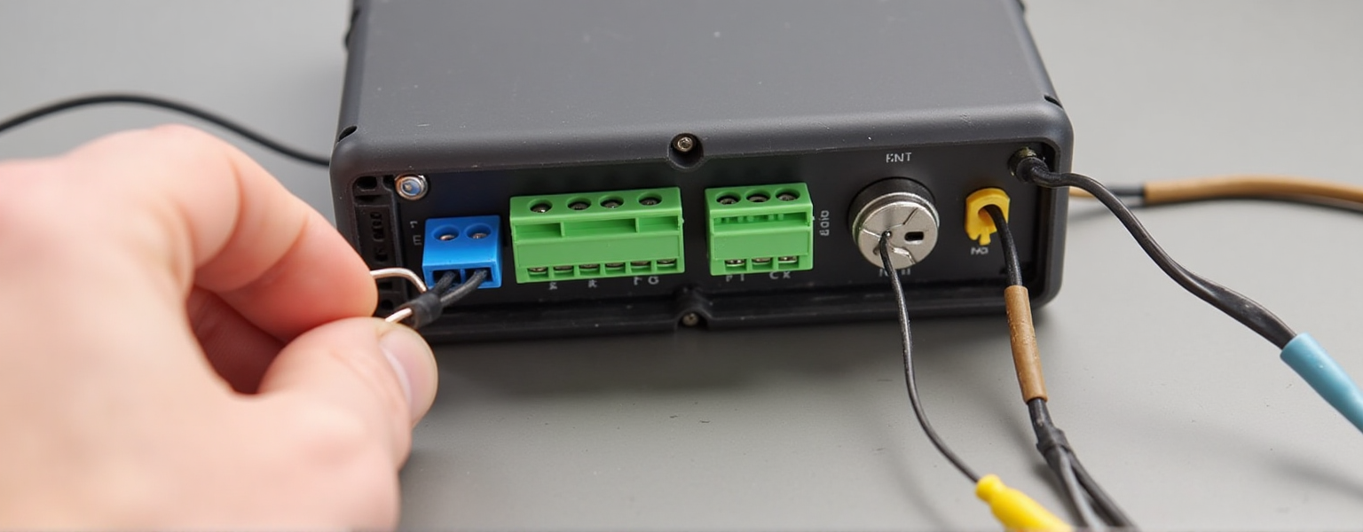
▲ Electrical maintenance:Wire Harness Use ▲
● Mechanical and Environmental Requirements
○ Temperature range: Standard PVC wires are suitable for -40°C to 105°C.
○ Protection rating: Waterproof and dustproof (IP67/IP68).
▲ Mechanical storage in a cold environment ▲
1.2 Wiring Harness Functional Definition
After clarifying the application scenarios, we further define the specific functions of the wiring harness.
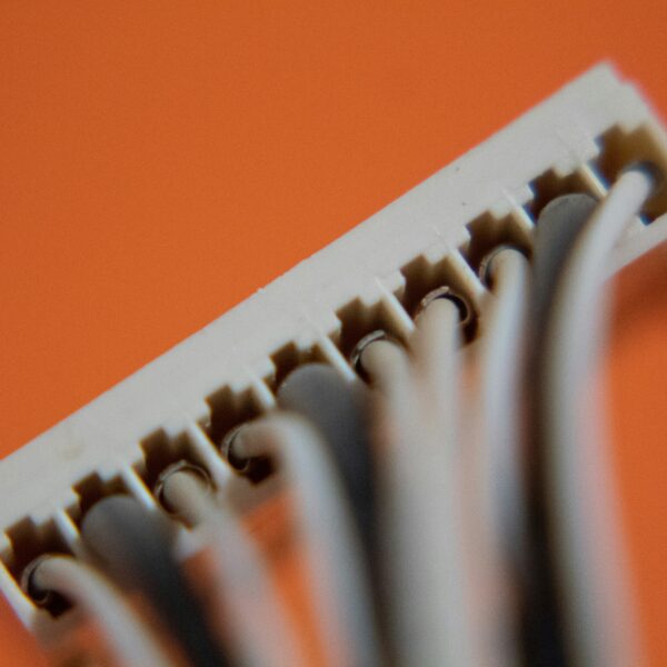
● Connection Methods
○ Terminal types: Crimp terminals (e.g., FAKRA, Mini-Fit), IDC (Insulation Displacement Connectors), solder terminals, etc.
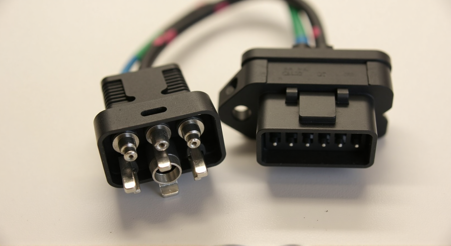
▲ Crimp terminal ▲
○ Connector Models: Automotive (e.g., TE Connectivity Deutsch, Molex MX150); Industrial (e.g., HARTING, JST); Waterproof connectors (e.g., IP68-rated AMPSEAL).
● Harness Layout
○ Length and Branches: Main trunk length, number of branches, and their positions (e.g., ECU branches, sensor branches in automotive harnesses).
○ Routing Methods: Open routing (e.g., internal equipment wiring); Enclosed routing (e.g., protected by corrugated tubes or braided sleeves).
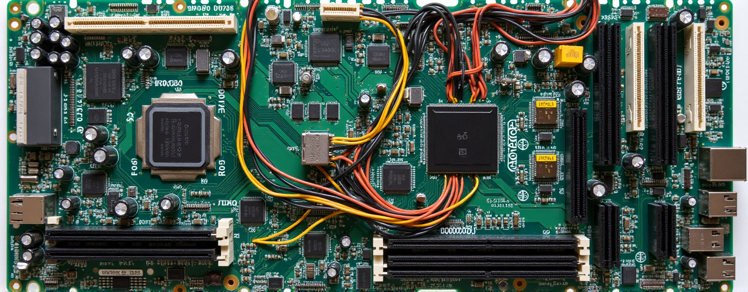
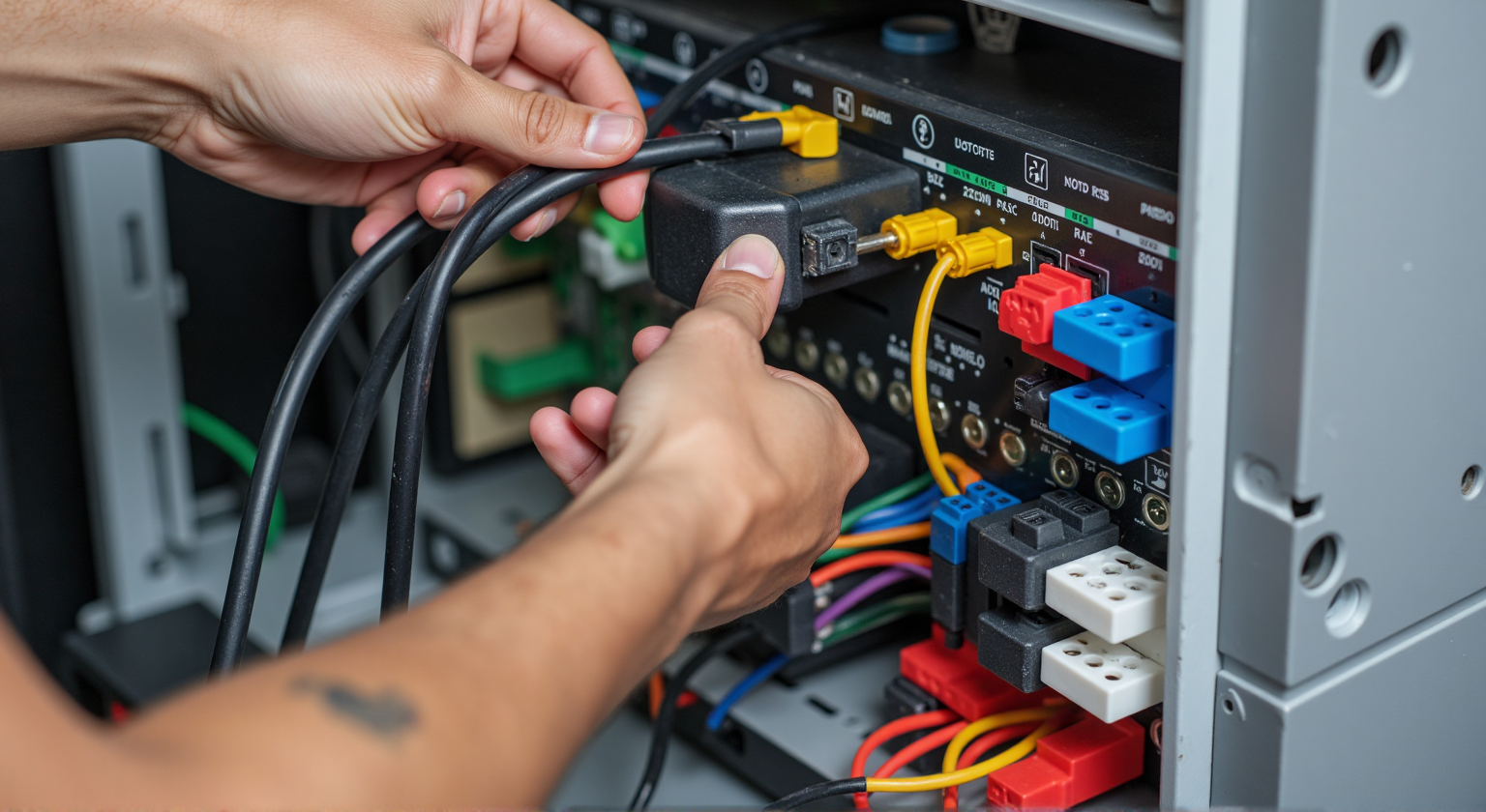
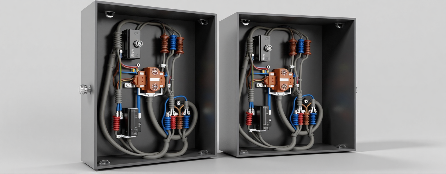
▲ Wiring harness behind the circuit board ▲
● Special Requirements
○ EMI/RFI Shielding: High-frequency signal lines may require foil or braided shielding.
○ Flame Retardancy: Compliance with UL94 V-0, IEC 60332, and other flame-retardant standards.
○ Color Coding: Facilitates installation and maintenance (e.g., industry-standard color coding for automotive harnesses).
1.3 Technical Feasibility Assessment
After collecting requirements, our engineering team conducts a technical feasibility analysis.
● Material and Technical Compatibility
○ Verify whether the supply chain can provide compliant wires, connectors, and sheathing.
○ Special requirements (e.g. super flexible wire, high temperature resistant silicone wire) may require customized procurement.
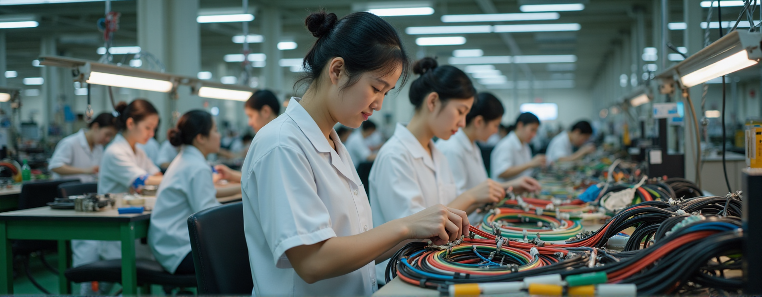
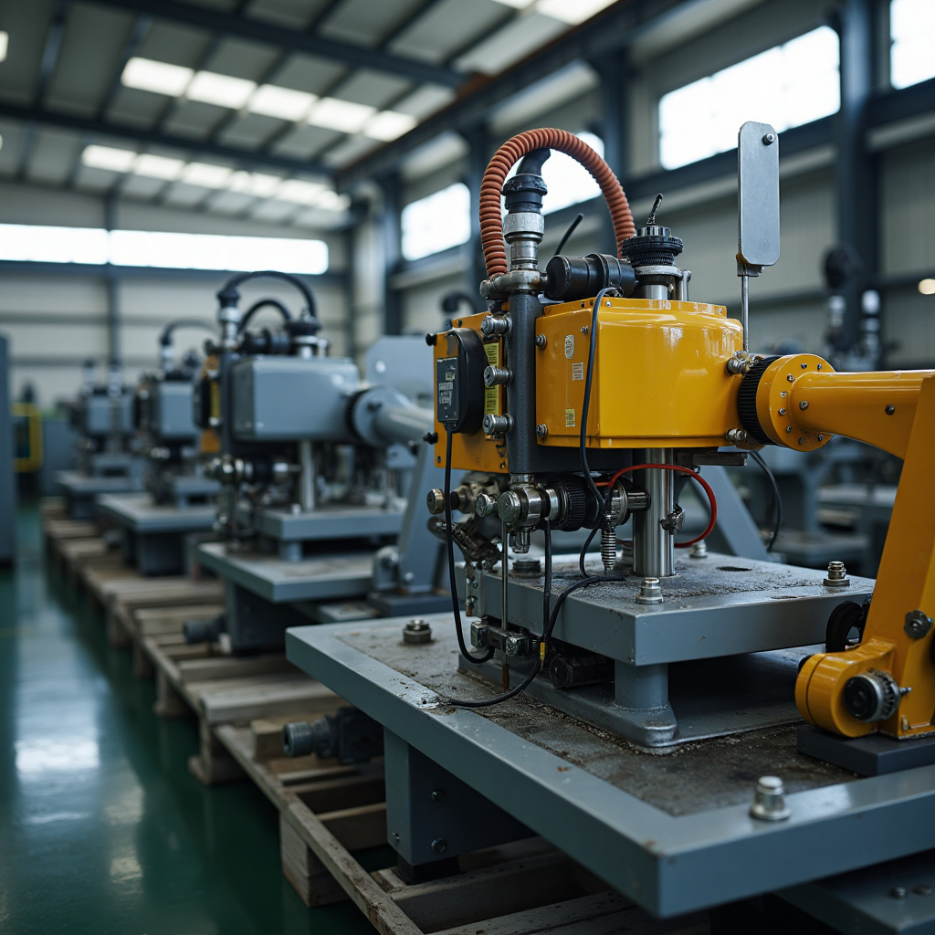
▲ Wiring harnesses are being processed at the factory ▲
● Cost and Lead Time Estimation
○ Provide initial quotes based on materials, process complexity, and quantity.
● Risk Analysis
○ Identify potential issues and develop contingency plans in advance.

▲ Engineers designing wire harness solutions ▲
Conclusion
○ Requirements analysis and specifications confirmation are key to successful customized wiring harnesses.
○ Through systematic communication and evaluation, we ensure every detail aligns with customer requirements.
○ In the next phase, we will proceed to the design stage, translating requirements into detailed harness drawings and 3D models.
▶▶ (Feel free to contact us to further discuss your wiring harness needs!) ◀◀
▶ Design Phase
The design phase is the core of customized wiring harness development, directly impacting product performance, reliability, and production costs.
Our engineering team systematically optimizes designs by integrating customer requirements, industry standards, and manufacturing feasibility.
2.1 Electrical Schematic Design
Objective: Define electrical connectivity logic to ensure signal transmission accuracy and stability.
● Circuit Topology Design
○ Create detailed electrical connection diagrams based on functional requirements.
○ Specify each wire’s function (e.g., power, signal, ground).
○ Label voltage, current, and signal types (e.g., high/low frequency, differential signals).

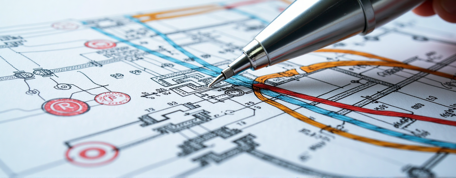
▲ Wiring diagram ▲
● Connector and Terminal Selection
○ Select appropriate connectors (e.g., AMP/TE for automotive, JST/Molex for industrial).
○ Choose terminal types (e.g., crimp, IDC, soldered).
○ Evaluate mating cycles, waterproof ratings (e.g., IP67/IP69K), and locking mechanisms (e.g., snap-fit, threaded).
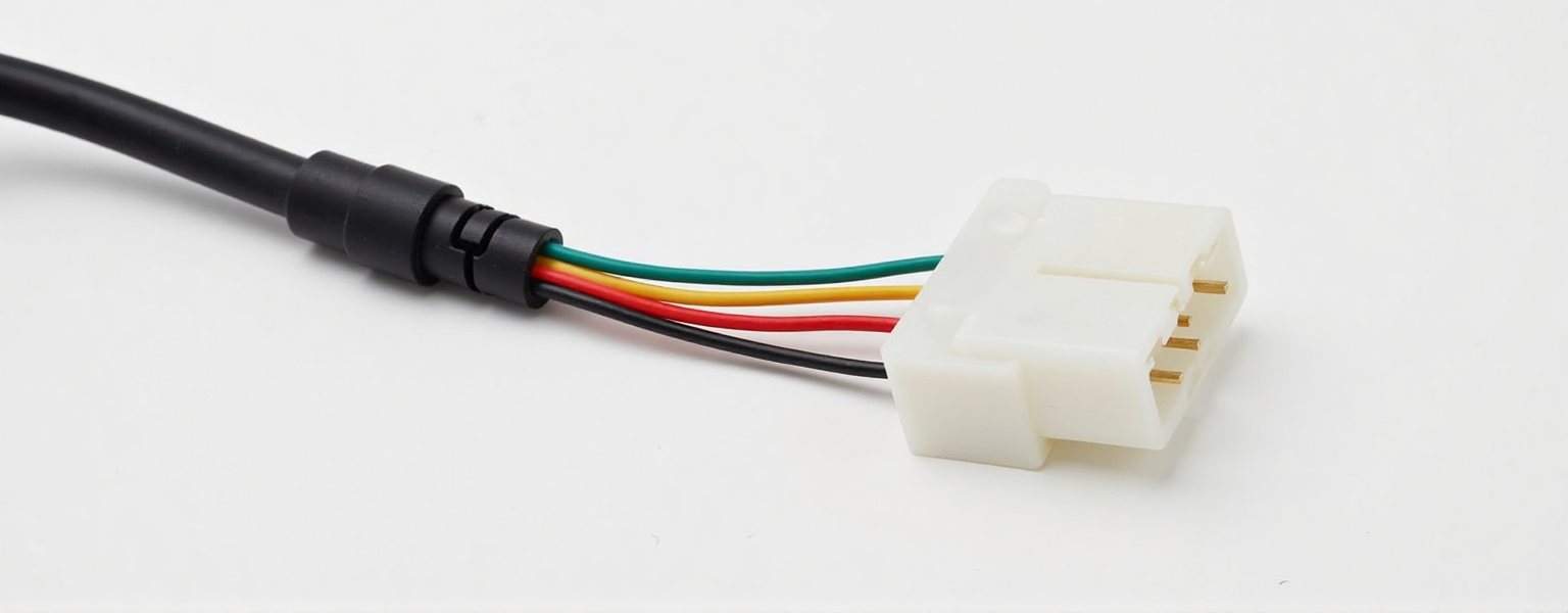
▲ Wire Harness Connectors ▲
● EMC/EMI Protection (If Required)
○ Use twisted pairs or shielded cables (e.g., braided, foil) for high-frequency signals.
○ Optimize grounding strategies to prevent signal interference.
2.2 3D/2D Harness Routing Design
Objective: Optimize spatial layout to ensure assemblability and avoid interference.
● 3D Modeling (Using SolidWorks, CATIA, etc.)
○ Simulate harness routing to prevent clashes with mechanical components.
○ Define bend radius (typically ≥5× wire diameter) to prevent fatigue fractures.
○ Design anchor points (e.g., zip ties, clips, grommets) for secure routing.
▲ 3D Effect Schematic ▲
● 2D Engineering Drawings
○ Specify critical dimensions (total length, branch lengths, terminal positions).
○ Provide flattened harness diagrams for production reference.
○ Note special requirements (e.g., color coding, label placement).
2.3 Material Selection
Objective: Balance cost, performance, and durability.
| Component | Options | Applications |
| Wires | · PVC (cost-effective) · Silicone (high-temp, 200°C) · Teflon (corrosion-resistant, high-frequency | Automotive, appliances, industrial |
| Insulation | · Heat shrink (localized protection) · Conduit (full-length protection) · Braided sleeve (abrasion-resistant) | Engine bays, robotic joints, outdoor |
| Connectors | · Waterproof (IP67) · High-temp (metal housing) · High-speed (USB3.0, HDMI) | EVs, medical, telecom |
| Shielding | · Foil (lightweight) · Copper braid (high EMI resistance) | Aerospace, military, precision instruments |
2.4 Design Validation (DFM & Simulation)
Objective: Identify issues early to minimize trial-and-error costs.
● Design for Manufacturing (DFM)
○ Verify terminal-wire compatibility (e.g., wire gauge vs. crimp die).
○ Assess assembly complexity (e.g., special tools/automation needs).
▲ Check wiring harness and terminal adaptability ▲
● Simulation Testing
○ Electrical: Simulate current distribution/temperature rise (ANSYS/SPICE).
○ Mechanical: Analyze vibration/tensile impacts (e.g., ISO 6722 for automotive).
○ Environmental: Simulate aging under heat, humidity, salt spray.
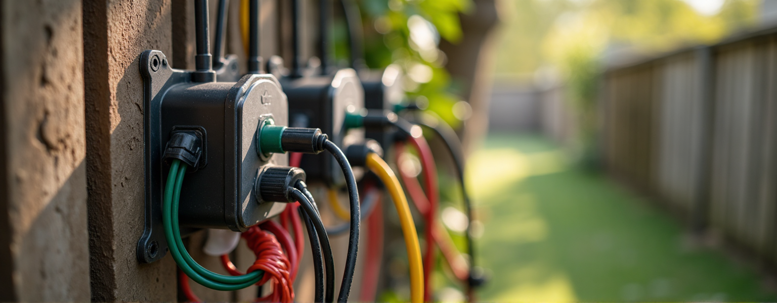
▲ Wiring harnesses in wet environments in the woods ▲
2.5 Deliver Technical Documentation
○ BOM (Bill of Materials): List all components, suppliers, and alternates.
○ Assembly Guide: Illustrated instructions with critical notes.
○ Test Specifications: Define QC checks (e.g., continuity, dielectric strength).
Key Takeaways
○ Design must balance electrical performance, mechanical reliability, and cost.
○ 3D modeling/simulation significantly reduces post-production risks.
○ Material selection dictates harness lifespan and environmental resilience.
▶▶ (Feel free to contact us to further discuss your wiring harness needs!) ◀◀
▶ Design Phase
After finalizing the design, we prioritize small-batch prototyping to validate feasibility.
3.1 Rapid Prototyping: From Design to Physical Sample
After finalizing the design, we prioritize small-batch prototyping to validate feasibility.
● The key objectives of this phase are:
○ Verify structural integrity: Do harness length and branch routing match the 3D model?
○ Assess assembly ease: Are connectors easy to mate/unmate? Are clips secure?
○ Validate material suitability: Do wires/sheathing meet temperature/abrasion requirements?
We use high-precision equipment (e.g., automatic crimping machines, ultrasonic welders) to ensure prototype consistency with mass production.
▲ Wiring harness drawings under the designer ▲
3.2 Performance Testing: Comprehensive Electrical & Mechanical Validation
Post-prototyping, we conduct multi-dimensional tests:
● Basic Electrical Tests
○ Continuity test: Verify no short/open circuits.
○ Insulation resistance test: Apply 500V DC to check insulation (≥100MΩ).
○ Dielectric strength test: Simulate high voltage (1500V AC/1min) for breakdowns.
● Environmental Tests
○ Thermal cycling (-40℃~125℃): Assess stability under extreme temperatures.
○ Damp heat test (85℃/85% RH): Evaluate moisture resistance.
○ Salt spray test (96hrs): Check metal terminals’ corrosion resistance.
● Mechanical Tests
○ Flex life test: Simulate repeated bending (100k cycles) for fractures.
○ Mating durability test: 500–5k cycles to verify terminal resilience.
○ Pull test: Apply 50N force to check terminal retention.
● Signal Integrity Tests (High-Frequency Applications)
○ Impedance matching (e.g., 90Ω differential).
○ Crosstalk and insertion loss measurements.
3.3 Customer Approval & Design Optimization
After testing, samples are shipped for customer validation:
● Fit issues: Adjust 3D routing for space/connector orientation.
● Performance upgrades: Modify wire gauge/material for higher current capacity.
▶▶ If a problem is found, we will provide a sample of the improved version as soon as possible. ◀◀

▲ Confirmation of the program ▲
3.4 Test Reports & Mass Production Standards
Final deliverables include detailed test reports (data/images/videos) and:
● Lock production parameters (e.g., crimp force, solder temperature).
● Define QC standards to ensure batch-to-sample consistency.
Why is Prototyping Critical?
While some clients prefer skipping prototyping, real-world data shows:
○ 30% of issues (e.g., poor contact, interference) are caught during prototyping.
○ Cost efficiency: Prototype fixes cost 1/10th of post-production rework.
▶▶ We adhere to the principle: “No mass production without qualified prototypes.” ◀◀
▶ Mass Production Preparation
After completing prototype testing and obtaining customer approval, the custom wiring harness project enters the mass production preparation phase.
The core objective of this phase is to ensure efficient, stable, and high-quality mass production.
4.1 Process Planning & Optimization
● Standard Operating Procedures (SOP) Development
○ Draft detailed “Harness Assembly Work Instructions” to standardize each step.
○ Define critical process parameters, such as:
▷ Wire cutting tolerance (e.g., ±1mm).
▷ Strip length (e.g., 3mm±0.2mm).
▷ Crimp height and pull force standards (e.g., ≥50N).
● Custom Tooling & Fixture Design
○ Design assembly fixtures to ensure precise wire positioning and consistency.
○ Deploy automated crimping machines to minimize human error and improve efficiency.
● Production Line Layout Optimization
○ Adopt U-shaped lines or flow production to reduce material handling waste.
○ Implement Poka-Yoke (error-proofing), including:
▷ Color coding to prevent incorrect terminal insertion.
▷ Barcode scanners to verify material batches and prevent mix-ups.

▲ Development of production planning ▲
4.2 Quality Control System Implementation
● Critical QC Checkpoints
| Process | Inspection Items | Methods | Standards |
| Wire Cutting | Length, Cut smoothness | Caliper/Visual inspection | ±0.5mm, No burrs |
| Wire Stripping | Strip length, Undamaged strands | Optical inspection | 3mm±0.2mm, No breaks |
| Crimping | Terminal height, Pull force | Pull tester | ≥50N, No deformation |
| Assembly | Connector sequence, Branch positioning | Manual check + Functional test | 100% Continuity |
● Automated Inspection Technologies
○ Continuity testers: 100% check for shorts/open circuits.
○ CCD vision systems: Detect crimping defects or misaligned pins.
● Quality Documentation
○ PFMEA (Process Failure Mode Analysis): Identify risks (e.g., loose crimps).
○ Control Plans (CP): Define inspection frequency/methods.
▲ Engineers take the planning program to check the equipment ▲
4.3 Supply Chain & Material Management
● Material Stocking Strategy
○ Core materials (e.g. terminals, rubber casing): sign long-term agreements with suppliers to ensure stable supply.
○ Special wires (e.g. high temperature silicone wires): stock up in advance to avoid delivery delays.
○ Alternative program reserve: For the shortage of materials, prepare alternate suppliers.
● Traceability System
○ Use barcodes/RFID to track material batches, production dates, and test data.gs).
4.4 Pilot Production (Small-Batch Validation)
Before formal mass production, 50~100 sets of trial production are usually carried out to verify:
✅ Whether the production line beat is up to standard (e.g. output per hour)
✅ Whether the defect rate is controllable (target ≤0.5%)
✅ Whether the packaging solution meets the transportation requirements
Conclusion
○ Mass production preparation is the final critical step to bring custom harnesses to market.
○ Through rigorous process planning, stringent quality control, and efficient supply chain management, we ensure every batch meets customer expectations.
▶ Mass Production & Delivery
After completing prototype testing and obtaining customer approval, customized wiring harnesses enter the mass production and delivery phase.
This stage directly impacts product quality consistency, delivery timelines, and customer satisfaction.
5.1 Large-Scale Production
● Production Equipment & Automation
○ Fully/Semi-automated equipment: Advanced machinery (e.g., automatic crimping machines, laser markers, harness assemblers) ensures efficiency and consistency.
○ Smart scheduling systems: Optimize production plans by order priority to minimize setup time and maximize capacity.
● Standardized Work Procedures (SOP)
○ Wire cutting/stripping: Maintain length tolerance (±1mm) and strip length per terminal specs.
○ Terminal crimping: High-precision dies with real-time monitoring (e.g., crimp height, ≥50N pull force).
○ Branching, bundling and assembling: Branching and positioning according to 3D wiring diagrams, fixed by using cable ties, rubber sleeves or heat-shrinkable tubes.
○ Connector assembly: Adopt error-proof design (e.g. anti-dull plug) to avoid misplugging.
● Batch Management & Traceability
○ Unique traceability codes (e.g., QR codes) track production dates, operators, and material batches.
5.2 Final Inspection & Testing
● 100% Continuity Test
○ Automated testers (e.g., Hi-Pot) verify no shorts, opens, or miswires.
○ Record test data and generate reports for customer review.
● Dimensional & Visual Checks
○ Calipers/profilometers measure critical dimensions (e.g., connector spacing, bend radius).
○ Dimension Inspection: Calipers/projector to measure critical parts (e.g. plug spacing, bending radius).
● Reliability Sampling Tests (Optional)
○ AQL-based sampling for salt spray (96hrs), thermal cycling (-40℃~125℃), etc.
5.3 Packaging & Logistics
● Custom Packaging Solutions
○ Anti-static packaging: Sensitive electronic wire harnesses are wrapped in anti-static bags or aluminum foil.
○ Anti-vibration protection: Lined with foam/blister box to avoid transportation damage.
○ Labeling and barcode: The outer box is labeled with product model, quantity, and PO number, supporting scanning into the warehouse.
● Global Logistics Support
○ VMI (Vendor Managed Inventory) reduces customer stocking burden.
○ Flexible transportation: Support air freight , sea freight or dedicated logistics, assist in customs clearance documents (e.g. RoHS, REACH certification).
5.4 After-Sales Support & Continuous Improvement
● Rapid Response System
○ Dedicated support team addresses delivery or technical issues within 24 hours.
○ Provide FAE (Field Application Engineer) support to assist installation or troubleshooting.
● Feedback & Optimization
○ Customer feedback drives improvements (e.g., enhanced mating cycles).
Conclusion
○ Mass production and delivery are the final execution stages of custom harness projects.
○ Our smart manufacturing + rigorous QC ensures precision at every step from factory to customer.
Contact us for tailored wiring harness solutions!!!
No comments to show.

Leave a Comment