Cooling Measures for Overloaded Harnesses

Table of contents
Material Optimization
1. High-Conductivity Materials
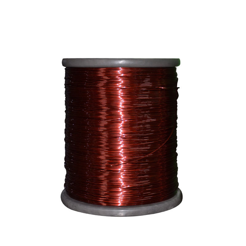
Key strategy: Reduce Joule heating by minimizing conductor resistance.
| Material Type | Characteristics and Advantages | Application Scenarios |
|---|---|---|
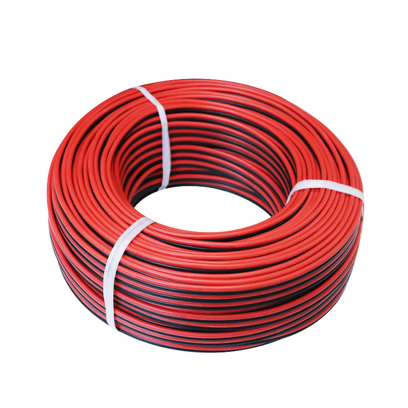
| Copper Alloy Wires | Low resistivity (<1.7×10⁻⁸ Ω·m), cost-effective for high-current applications. | EV high-voltage harnesses, industrial power distribution. |
| Silver-Plated Wires | 30%~50% lower contact resistance, anti-oxidation, stable for high-frequency signals. | Aerospace, precision instrument harnesses. |
| Nickel-Based Alloys | Withstand >400°C, excellent creep resistance. | High-temperature environments (e.g., engine compartments). |
2. Insulation & Thermal Management Materials
Goal: Enhance thermal conductivity of insulation layers while ensuring electrical safety.
(1)High-Temperature Insulation
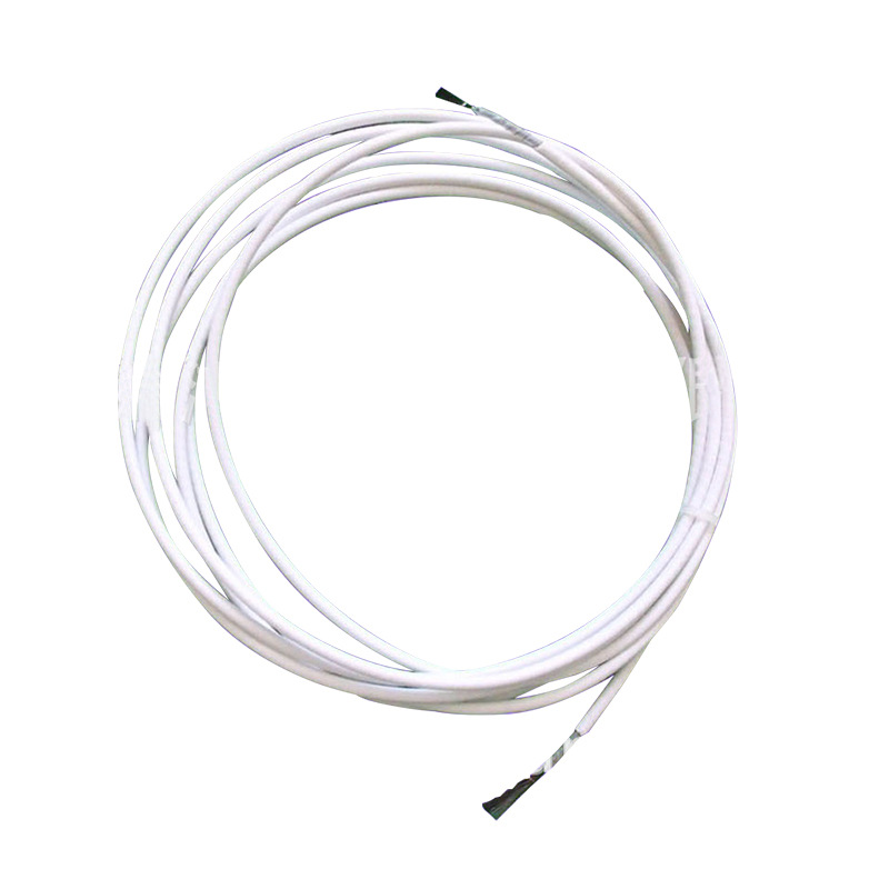
- PTFE:Temperature range: -200℃~260℃, chemically inert, low friction coefficient.
- Silicone Rubber:High flexibility, 180℃~250℃ resistance, ideal for complex bending harnesses.
(2)Thermal Conductivity Enhancement
| Methodology | Principle | Effect |
|---|---|---|
| Alumina Particles | Mix 10%~30% alumina (thermal conductivity 30 W/m·K). | 3~5× higher conductivity, 15%~20% cost increase. |
| Thermal Grease Coating | Coat harness with boron nitride-enhanced grease. | 40%~60% lower interfacial thermal resistance, requires maintenance. |

3. Innovative Composite Materials
| Materials | Structural Design | Comprehensive Advantages |
|---|---|---|
| Metal-Polymer Laminates | Alternating copper foil and polyimide layers. | High thermal conductivity (5~8 W/m·K) + electrical insulation. |
| Carbon Fiber-Reinforced Wires | Carbon fiber coating on copper core. | 30% weight reduction, 10%~15% higher current capacity. |
▶ Summary
• Cost-effective: Copper alloy + silicone rubber + alumina filler
• Extreme conditions: Silver-plated wires + PTFE + liquid cooling
Structural Design
1. Layout Optimization
Objective: Minimize heat concentration and enhance cooling efficiency through spatial distribution optimization.
(1)High-Temperature Insulation
- Wire Harness Pitch Control: Maintain spacing ≥2× wire diameter (or ≥10 mm) between adjacent harnesses.
- Partition Management: Separate high-power and low-power harnesses in different channels.
(2)Layered Isolation
| Hierarchical Design | Functional Description | Application Examples |
|---|---|---|
| EM Shielding Layer | Metal braid layer blocks EMI and reduces eddy current heating. | High-frequency communication harnesses, automotive sensor harnesses. |
| Thermal Barrier Layer | Ceramic fiber or aerogel layers reflect radiant heat. | Engine compartment harnesses, industrial high-temperature equipment. |

2. Heat Dissipation Structures
Core principle: Accelerate heat transfer and dissipation via structural design.
(1)Passive Cooling
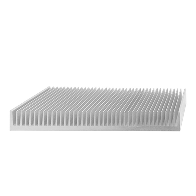
- Metal Heat Sinks:
Wrap harnesses with aluminum/copper fins to enhance natural convection.
Example parameters: Fin thickness 0.5~1 mm, density 5~8 fins/cm. - Corrugated Conduit Design:
Corrugated tubes (nylon or metal) increase turbulent airflow for cooling.
(2)Active Cooling Integration
| Structural Solutions | Working Principle | Applicable Scenarios |
|---|---|---|
| Embedded Liquid Channels | Micro liquid channels in cable jackets circulate coolant. | Data center harnesses, EV battery pack harnesses. |
| Airflow Guide Grooves | Surface grooves guide airflow with fans (≥3 m/s). | Server racks, industrial control cabinets. |
3. Modular Design
Advantage: Reduce localized heat load and simplify maintenance.
| Module Type | Design Features | Cooling Benefits |
|---|---|---|
| Detachable Connectors | Plug-in terminals allow quick disconnection of high-heat modules. | 50% faster cooling maintenance. |
| Segmented Shielding Covers | Modular metal covers enable localized cooling. | 15%~20% hotspot temperature reduction. |
4. Mechanical-Thermal Co-Design
Key focus: Balance mechanical strength and thermal performance.
- Thermal Expansion Compensation Structures: Spring coils or elastic brackets compensate for thermal expansion (≥5 mm/m).
- Lightweight openwork design: Lightweight honeycomb structures reduce weight by 30% and improve heat dissipation.

▶ Summary
The structural design achieves efficient cooling through space layout optimization, heat dissipation structure innovation and modularity. For example:
- Layered Isolation + Embedded Liquid Channels
- Corrugated Tubes + Airflow Guide Grooves
Active Cooling Systems
1. Forced Air Cooling
Advantage: Low cost and easy deployment through enhanced airflow.
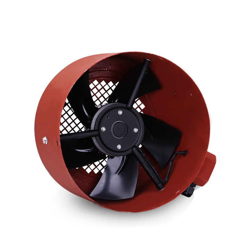
(1)Integrated Fans
- Axial Fans: Mounted near harnesses with 2~5 m/s airflow, improving efficiency by 30%~50%.
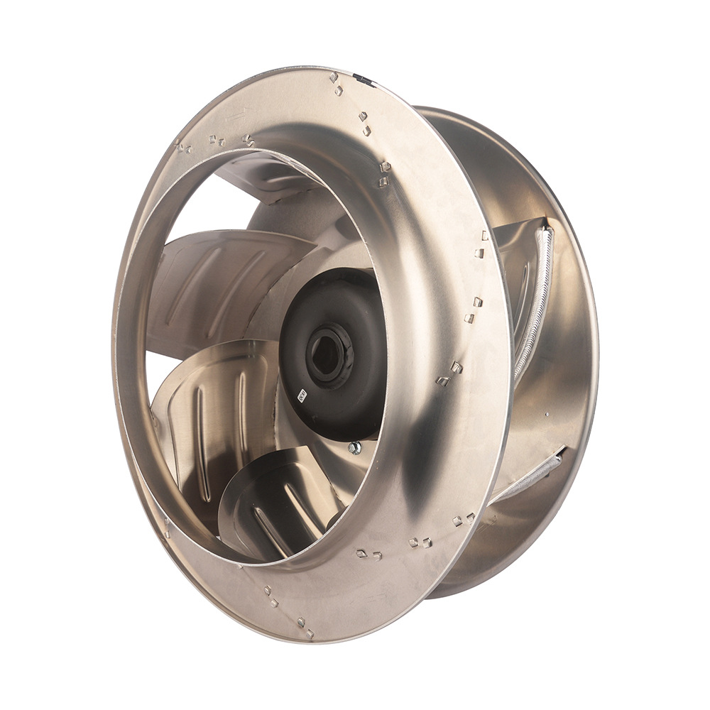
Applications: Server racks, EV battery harnesses. - Centrifugal Fans: High-pressure airflow penetrates dense harness areas (pressure >200 Pa).
Applications: Industrial control cabinets, aerospace systems.
(2)Airflow Path Optimization
| Design Methodology | Functional Description | Performance Enhancement |
|---|---|---|
| Air Guide Plates | Direct airflow to high-heat harnesses (e.g., copper plates). | Local temperature reduction: 15~25℃. |
| Honeycomb Ducts | Hexagonal structures reduce turbulence and distribute airflow evenly. | Overall efficiency improvement: 20%~30%. |
2. Liquid Cooling
Superiority: Heat transfer capacity significantly exceeds air cooling.
(1)Liquid Cooling Solutions Comparison
| Type | Principle of operation | Coolant | Scenario |
|---|---|---|---|
| Microchannel Cold Plates | Metal plates with microchannels (0.1~0.5 mm) attached to harness surfaces. | Water-glycol mixture | Data centers, high-power electronics. |
| Immersion Cooling | Submerge harnesses in dielectric fluid (e.g., fluorocarbon). | Fluorocarbon/Mineral oil | Supercomputers, energy storage systems. |
(2)Key Parameters
- Flow rate: 0.5~2 L/min, adjusted based on thermal load.
- Temperature gradient: Inlet-outlet ΔT ≤10℃ to prevent local boiling.
3. Phase Change Cooling
Advantage: Absorb large amounts of heat via latent heat, ideal for transient overloads.
(1)PCM Types
| Material | Phase Transition Temperature | Latent heat capacity | Integration method |
|---|---|---|---|
| Paraffin | 40~80℃ | 150~250 kJ/kg | Embedded in harness sheath layers. |
| Metal Alloys | 100~300℃ | 200~400 kJ/kg | Fins or wraps around harnesses. |

(2)Heat Pipe Technology
- Principle: Evaporation-condensation cycle of working fluid (e.g., water/ammonia).
- Example: 6 mm copper heat pipe, heat transfer >100 W.
4. Hybrid Cooling Systems
Goal: Balance performance and cost by combining multiple cooling methods.
| Combined Solutions | Components & Benefits | Application Cases |
|---|---|---|
| Air + Liquid Cooling | Air cooling at low load, liquid cooling activated at high load. | Hybrid EV harnesses, smart grid systems. |
| PCM + Heat Pipes | PCM absorbs peak heat, heat pipes export residual heat. | 5G base station harnesses, industrial robots. |
▶ Summary
The selection of an active cooling system requires a combination of Heat Load Intensity, Environmental Constraints and Cost-Effectiveness:
Monitoring & Protection
Objective: Prevent harness failure caused by overheating through real-time monitoring and intelligent protection.
1. Real-Time Monitoring
(1)Temperature Sensors
| Type | Principle | Precision | Application Scenarios |
|---|---|---|---|
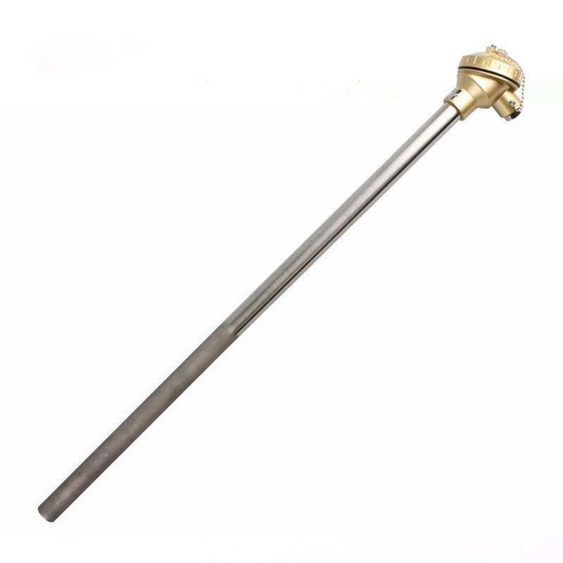
| Thermocouples | Based on Seebeck effect (temperature difference). | ±1.5℃ | High-temperature harnesses (>300℃). |
| PT100 Sensors | Linear resistance variation (100Ω at 0℃). | ±0.3℃ | Precision systems (e.g., medical devices). |
| Fiber Optic Sensors | Light signals modulated by temperature, EMI-resistant. | ±0.5℃ | High-voltage substations, explosive environments. |
(2)Multi-Parameter Monitoring
- Current/Voltage Monitoring: Hall sensors (±1% accuracy) detect overload currents.
- Thermal Imaging: Infrared cameras (resolution ≤0.05℃) scan hotspots periodically
2. Overload Protection
(1)Smart Circuit Breakers
| Function | Trigger conditions | Response time |
|---|---|---|
| Dual Thresholds (T & I) | T >85℃ or I >150% rated current. | ≤50 ms |
| Auto-Reset | Auto-reconnect after cooling (ΔT <10℃). | 5~10 min |
(2)Fuses & Current Limiters
| Type | Characteristic | Scenario |
|---|---|---|
| Fast-Acting Fuses | Response <1 ms, breaking capacity 10 kA. | Short-circuit protection (e.g., battery harnesses). |
| PTC Resettable Fuses | Resistance spikes during overload, self-resetting. | Consumer electronics, low-voltage automotive harnesses. |
(3)Dynamic Load Management
- Priority Control: Shut down non-critical loads via CAN/PLC.
- Current Balancing: Distribute current among parallel harnesses (<5% deviation).
3. Data Analytics & Alerts
(1)Predictive Maintenance
| Technologies | Data Sources | Early Warning Indicators |
|---|---|---|
| Machine Learning | Historical T, I, and environmental data. | Temperature rise rate >2℃/min or aging index >80%. |
| Digital Twin | 3D harness model + real-time sensor data. | Alert when simulation-actual ΔT >5℃. |
(2)Remote Monitoring Platforms
- Cloud Dashboard: Visualize temperature distribution, load status, and trends.
- Multi-level alarms:
- Level 1 (Yellow): 80% threshold reached, notify operators.
- Level 2 (Red): Threshold exceeded, activate protection.

▶ Summary
The monitoring and protection system builds a closed-loop security system through Real-Time Sensing, Intelligent Decision-Making and Rapid Response. Typical programs include:
- Fiber Optic Sensors + Smart Breakers + Digital Twin
- In-vehicle scenarios:PTC Fuses + CAN-Based Load Management
Maintenance Management
Objective: Extend harness lifespan and sustain cooling performance through systematic maintenance.
1. Scheduled Maintenance Plans
Core principle: Prevent cooling failure caused by aging or contamination.
(1)Scheduled Maintenance Plans
| Maintenance tasks | Frequency | Tools & Methods | Target results |
|---|---|---|---|
| Insulation Inspection | Every 6 months | Visual check + Megger (>100 MΩ). | Prevent leakage and short circuits. |
| Cooling Structure Cleaning | Every 3 months | Compressed air (≤0.3 MPa) or ultrasonic cleaning. | Restore >90% cooling efficiency. |
| Connection Tightening | Annual | Torque wrench (5~10 N·m per specs). | Reduce contact resistance by 10%~20%. |
2. Cleaning & Contamination Control
(1)Dust & Oil Removal
- Dry Cleaning: Anti-static brushes or vacuums for surface dust.
- Wet Cleaning: Isopropyl alcohol (≥99%) for oil stains, avoiding insulation damage.
(1)Anti-Corrosion Measures
| Methods | Scenario | Effect |
|---|---|---|
| Conformal Coating | High humidity/salt spray environments. | Reduce corrosion by 70%~90%. |
| Sealed Terminal Boxes | Chemical or dusty areas. | >95% contaminant blockage. |
3. Load Management & Upgrades
(1)Load Balancing Strategies
- Dynamic Allocation: Adjust loads based on real-time temperature (<5% deviation).
- Capacity Upgrade: Replace with larger cross-section cables (e.g., 4→6 mm²).
(2)Overload History Analysis
| Parameters | Analysis Tools | Optimization Actions |
|---|---|---|
| Peak Current Logs | Data loggers (≥1 kHz sampling). | Adjust breaker thresholds or add redundancy. |
| Temperature Rise Curves | Thermal simulation software. | Optimize cooling structures or boost cooling power. |

▶ Summary
Maintenance management achieves sustainable cooling effectiveness through Preventive Maintenance, Data-Driven Decisions and Capacity Building. Typical Scenario Applications:
- Quarterly Cleaning + Load Analysis + ANSYS Simulation
- In-vehicle scenarios:Annual Tightening + Dynamic Load Allocation
Es sind keine Kommentare vorhanden.


Kommentar verfassen