Shielded vs Unshielded: Choosing Cables for Telecom Devices
In telecommunications infrastructure, the choice between shielded (STP) and unshielded (UTP) cables is pivotal for balancing electromagnetic interference (EMI) resistance, cost efficiency, and deployment flexibility. This article dissects structural distinctions, performance benchmarks, and scenario-based guidelines to empower informed decisions in modern network design.
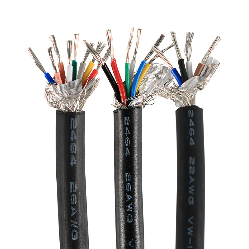
Table of contents
Ⅰ. Structural Differences
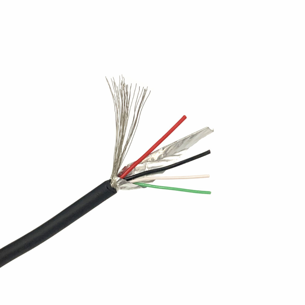
The physical structures of Shielded Twisted Pair (STP) and Unshielded Twisted Pair (UTP) cables have significant differences, which directly affect their performance and application scenarios. The following is a detailed comparison:
1. Core Structural Comparison
| Component | STP Shielded Twisted Pair | UTP Unshielded Twisted Pair |
|---|---|---|
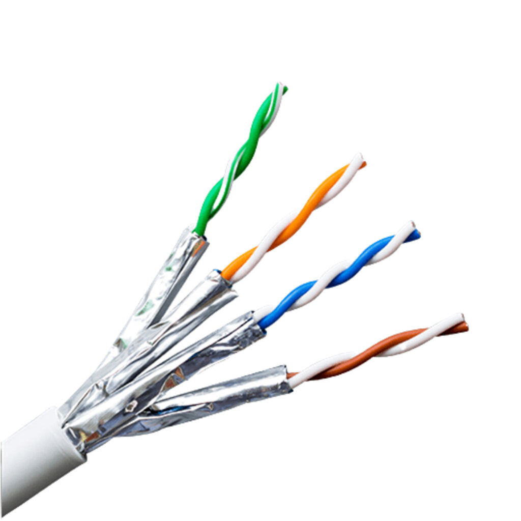
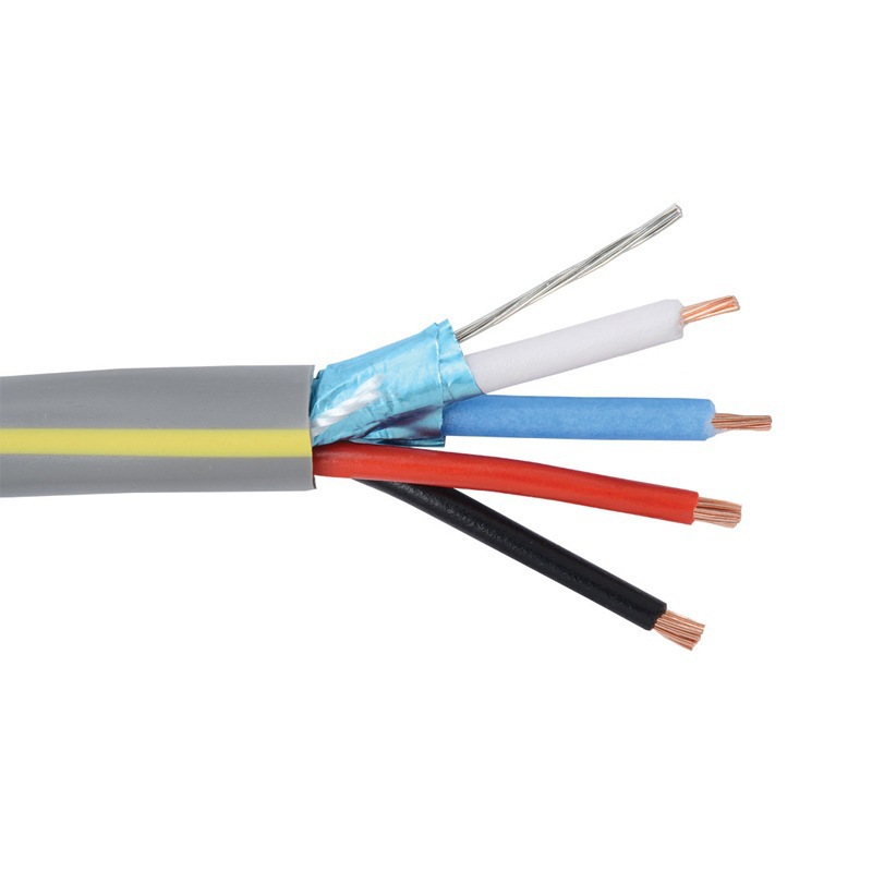
| Shielding Layer | Includes a metal foil (such as aluminum foil) or braided mesh shielding layer, which wraps around the wire pairs or the entire cable to suppress external electromagnetic interference (EMI) and radio frequency interference (RFI). | No additional shielding layer; relies solely on the twisted structure of the wire pairs to reduce internal crosstalk. |
| Insulation | Each twisted pair is individually wrapped with an insulating layer, and some models add an outer sheath for the overall shielding layer. | Only plastic insulation layers (such as polyethylene, PE) are used between the twisted pairs, with no overall shielding. |
| Conductor | Typically uses thinner copper conductors (such as 24 AWG) to accommodate the multi-layer shielding structure. | Thicker conductors (such as 23 AWG) with no shielding layer restrictions, resulting in a larger wire diameter. |
| Jacket | The outer sheath is thicker, and some models add tensile fibers or flame-retardant materials (such as LSZH). | The sheath is thinner and more flexible, making it easier to bend and install. |
| Grounding | Requires grounding through a dedicated grounding wire or connector (such as a metal RJ45); otherwise, the shielding will fail. | No grounding required, making installation simpler. |
2. Core Structural Comparison
| STP Subtype | Structure | Application Scenario |
|---|---|---|
| FTP (Foiled Twisted Pair) | Single-layer aluminum foil wraps all wire pairs, with lower cost. | Medium interference environments (such as office buildings near elevator areas). |
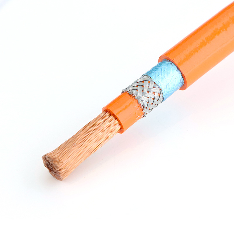
| S/FTP (Shielded/Foiled TP) | Each wire pair is individually shielded with aluminum foil + overall braided mesh shielding, providing the strongest interference resistance. | Extreme interference environments (such as factories, substations). |
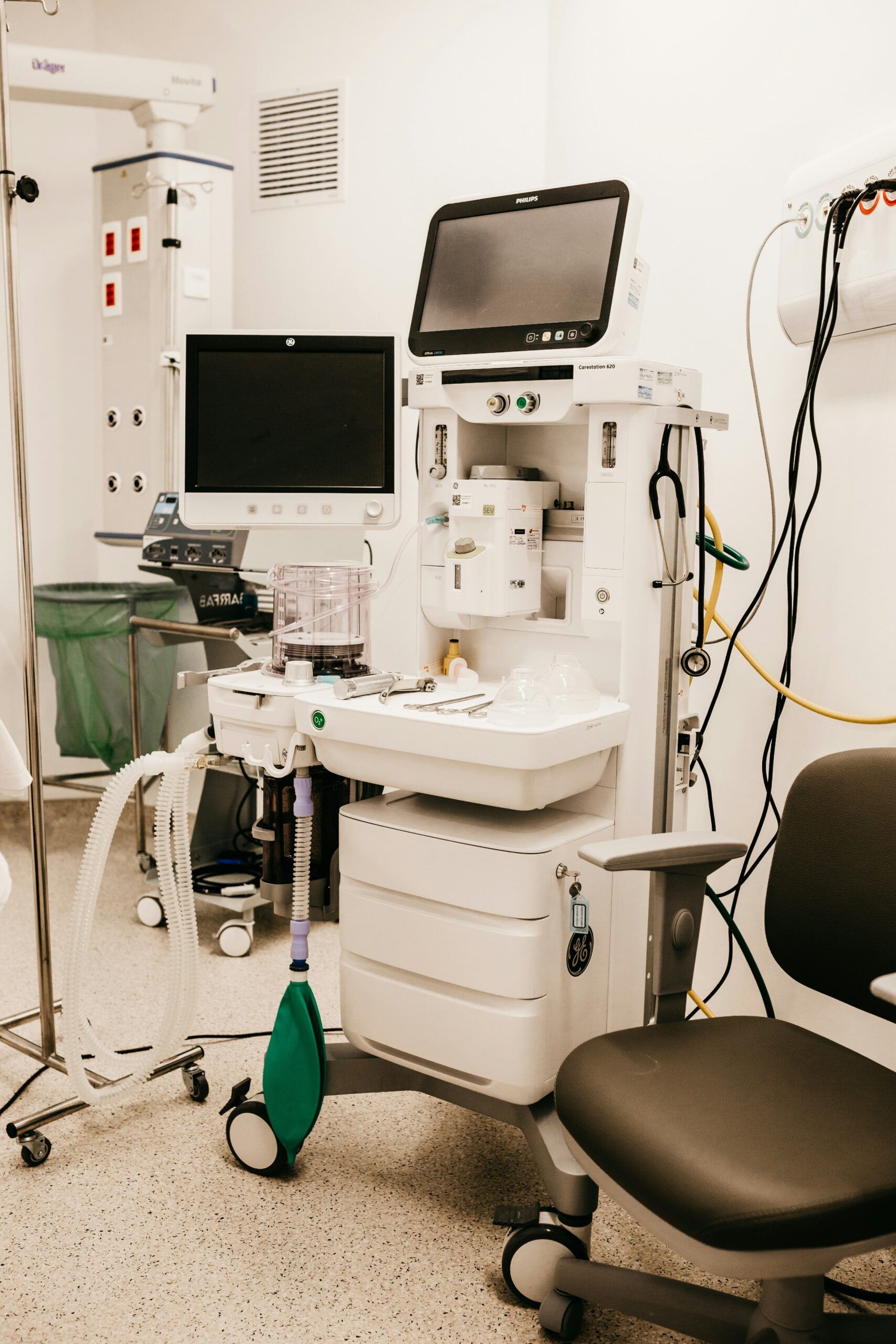
| U/FTP (Unshielded/Foiled TP) | Only each wire pair is individually shielded with aluminum foil, with no overall shielding layer. | Local high-frequency interference (such as around medical equipment). |

3. Summary of Key Differences
| Aspect | STP Advantage | UTP Advantage |
|---|---|---|
| Interference Resistance | The shielding layer can reduce external interference by over 90% (test value). | Relies on the twisted structure to reduce internal crosstalk, with weak external interference suppression. |
| Weight and Flexibility | Weight increases by 20%-30%, with a larger bend radius (follow the 10:1 rule). | Lightweight design, with a smaller bend radius (4:1), suitable for confined spaces. |
| Signal Attenuation | The shielding layer may introduce additional capacitance, resulting in slightly higher attenuation of high-frequency signals (>500MHz). | No shielding layer capacitance effect, with more stable short-distance high-frequency signals. |
| Standard Compliance | Must comply with strict grounding standards such as IEC 61156-5/6. | Complies with the universal TIA/EIA-568 standard, with strong compatibility. |
4. Structural Diagram (Text Description)
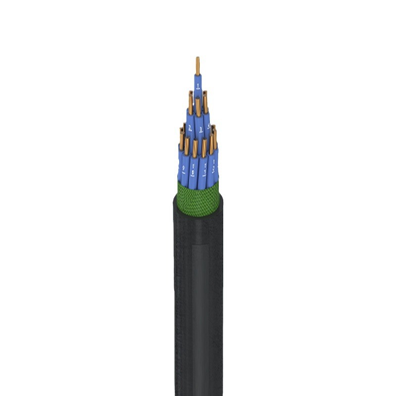
- STP:
- Outer jacket → Overall shielding layer (aluminum foil/braided mesh) → Twisted pairs (individually insulated) → Copper conductors
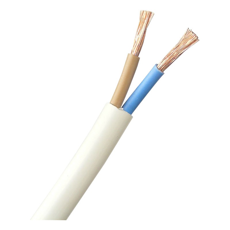
- UTP:
- Outer jacket → Twisted pairs (only plastic insulation) → Copper conductors
※ Through the analysis of structural differences, it can be seen that STP achieves strong interference resistance through multi-layer shielding, but sacrifices cost and installation convenience; UTP meets conventional needs with a simplified design and is a cost-effective universal choice.
Ⅱ. Performance Comparison
Shielded (STP) and unshielded (UTP) cables have significant performance differences in practical applications, which directly affect the stability and efficiency of telecommunication equipment. The following is a comparison of key indicators:
1. Anti-Interference Capability
| Interference Type | STP Performance | UTP Performance | Testing Standard |
|---|---|---|---|
| Electromagnetic Interference (EMI) (e.g., motors, transformers) | The shielding layer can attenuate interference by 60-90 dB (at 100 MHz) | Relies solely on the twisted structure, attenuation <30 dB | IEC 61000-4-6 |
| Radio Frequency Interference (RFI) (e.g., 5G base stations, WiFi) | Aluminum foil shielding can reflect 90% of high-frequency signals | High-frequency signals easily couple to the cable, requiring additional filtering | ANSI/TIA-1152 |
| Crosstalk | Each pair is individually shielded, near-end crosstalk (NEXT) < -70 dB | Higher crosstalk between adjacent pairs (NEXT ≈ -50 dB) | TIA-568.2-D |
2. Transmission Characteristics
| Parameter | STP | UTP | Application Scenario |
|---|---|---|---|
| Maximum Bandwidth (e.g., CAT6A) | 500 MHz (shielding optimizes high-frequency stability) | 500 MHz (unshielded performs better over short distances) | Data center backbone |
| Signal Attenuation (100 meters @ 100 MHz) | 20.1 dB (slightly increased loss due to shielding layer capacitance) | 19.8 dB (slightly lower loss without shielding layer) | Long-distance transmission |
| Bit Error Rate (BER) | ≤10⁻¹² (remains stable under strong interference) | ≤10⁻¹⁰ (significantly worse in high-interference environments) | Industrial control systems |
3. Security & Stability
| Scenario | STP Solution | UTP Solution |
|---|---|---|
| High-Security Networks (government, finance) | The shielding layer prevents electromagnetic leakage (TEMPEST protection), complying with NIST SP 800-88 standards | Relies on AES-256 encryption technology, with weak physical layer protection |
| High-Temperature/Humid Environments | The metal shielding layer blocks moisture, and flame-retardant jackets (such as LSZH) can withstand temperatures up to 75°C | Ordinary PVC jackets age easily (only withstand temperatures up to 60°C) |
| Vibration Environments (vehicle-mounted, factories) | Braided mesh shielding layer resists mechanical stress, providing more reliable connections | Long-term vibration can easily cause RJ45 connectors to loosen |

4. Cost-Effectiveness Analysis
| Cost Dimension | STP | UTP |
|---|---|---|
| Initial Purchase Cost (CAT6A/meter) | $2.5-$4.0 (including shielding materials and grounding components) | $1.2-$2.0 (only basic materials) |
| Installation and Maintenance Costs | Requires specialized grounding tools and labor (+30% labor cost) | Plug-and-play, saving 50% deployment time |
| Lifecycle Cost | Over 10 years (interference resistance extends equipment life) | 6-8 years (interference may accelerate equipment failure) |
▷ Overall Performance Rating (1-5 Points)
| Category | STP | UTP | Notes |
|---|---|---|---|
| Anti-Interference | 5 | 3 | STP wins in EMI/RFI scenarios |
| Transmission Distance | 4 | —— | —— |
▶ Conclusion:
• Priority STP: High interference (factories/hospitals), long-distance backbone network, high security requirement scenarios.
• Priority to UTP: short distance office network, cost-sensitive projects, low interference civilian environment.
• Hybrid solution: Data center can use “STP backbone + UTP access layer” combination, balancing performance and cost.
Ⅲ. Application Scenarios
Shielded (STP) and unshielded (UTP) cables have significantly different applicabilities in various scenarios. The following is a targeted analysis of typical application scenarios:
1. Scenario Classification and Cable Selection Table
| Scenario | Recommended Cable | Key Requirements | Technical Support |
|---|---|---|---|
| Industrial Automation (e.g., robot control, PLC systems) | STP (S/FTP type) | Withstand high-frequency electromagnetic interference (EMI ≥ 60 dB) from motors and inverters | IEC 61000-6-2 Industrial Interference Standard |
| Data Center Backbone | STP (Cat6A and above) | 10Gbps long-distance transmission (>55 meters), reduce bit error rate (BER < 10⁻¹²) | TIA-942 Data Center Standard |
| Outdoor Telecom Cabinets | STP (with metal braided mesh shielding) | Lightning protection (voltage ≥ 6kV), moisture resistance | GR-487 Outdoor Equipment Environmental Standard |
| Hospital MRI Rooms | STP (double shielding + drain wire) | Isolate strong magnetic field interference (≥1.5T), avoid data packet loss | ISO 13485 Medical Device Compatibility |
| Smart Home IoT | UTP (Cat6) | Short distance (<30 meters), cost-effective, supports PoE power supply | TIA-568.2-D Residential Wiring Standard |
| Military Communications | STP (full shielding + armored jacket) | Protect against electromagnetic pulses (EMP), resist physical damage | MIL-STD-461G Military Electromagnetic Standard |


2. Performance Comparison in Typical Scenarios
| Scenario Parameters | STP Application Solution | UTP Application Solution |
|---|---|---|
| Factory Production Line (dense interference sources) | Signal stability: 99.99% Mean time between failures: >5 years Maintenance cost: $200/year/node | Signal stability: 95% Mean time between failures: 2-3 years Maintenance cost: $500/year/node |
| Office Local Area Network (low interference) | Over-designed, 40% cost increase Poor grounding may cause failures | Optimal cost-effectiveness Deployment speed increased by 50% |
| Traffic Signal Control System | Resistant to vehicle radio interference (5G/LTE) Supports wide temperature range (-40°C~85°C) | Requires additional signal filters Limited temperature adaptability (0°C~60°C) |
3. Hybrid Deployment Cases
| Hybrid Case | STP Usage Ratio | UTP Usage Ratio | Advantages |
|---|---|---|---|
| Smart Factory Network | 70% (backbone/control layer) | 30% (sensor access layer) | Interference resistance in backbone, cost reduction at endpoints |
| 5G Base Station Backhaul Network | 100% (fiber + STP hybrid cable) | 0% | Fiber for primary transmission, STP backup link for lightning protection |
| Airport Terminal Network | 50% (security check/scheduling area) | 50% (waiting area WiFi) | Shielding in high-security zones, economical deployment in public areas |
▷ Selection Decision Tree
- Is there any of the following interference?
- Yes → Choose STP: Industrial equipment/Medical instruments/Military EMP
- No → Proceed to Step 2
- Is the transmission distance >55 meters?
- Yes → Choose STP (Cat6A and above)
- No → Proceed to Step 3
- Is PoE power supply required?
- Yes → Choose UTP (Cat5e and above)
- No → Choose UTP (Basic Cat6)
▶ Scenario Adaptation Conclusion
• STP: irreplaceable in extreme environments (high temperature, high humidity, strong interference), especially in line with the stringent ISO/IEC 11801-1 Class EA standards.
• UTP: still the mainstream choice for civil and light industrial scenarios, with more than 75% of the global structured cabling market share (BICSI 2023 report).
• Hybrid Deployment: Balances performance and cost with typical savings of 15%-25% through “core shielded + edge unshielded” architecture.
Ⅳ. Selection Guidelines
The selection of shielded (STP) and unshielded (UTP) cables should be based on a comprehensive decision-making process that considers environmental requirements, technical specifications, and cost-effectiveness. The following is a structured selection framework:
1. Core Decision Factors
| Factor | STP Preferred Scenarios | UTP Preferred Scenarios | Verification Method |
|---|---|---|---|
| EMI/RFI Interference Intensity | Factory workshops (>30 V/m), medical equipment areas (near MRI), around 5G base stations | Offices (<3 V/m), homes, environments without large motors | Electromagnetic field strength meter testing |
| Transmission Distance | >55 meters (Cat6A and above require shielding to ensure 10Gbps stability) | <30 meters (PoE power supply or Gigabit network) | Network planning software simulation |
| Security Level | Government/military facilities (TEMPEST protection), financial data centers (PCI-DSS compliance) | Ordinary commercial networks (HTTPS encryption is sufficient) | Security audit standard comparison |
| Budget Limitation | Allow a 40%-60% increase in unit price (including grounding system) | Require a cost per port of <$50 (for small and medium-sized projects) | Cost-benefit analysis (CBA) |
| Temperature/Humidity | High temperature (>60°C), high humidity (>85% RH), outdoor lightning protection | Controlled environment (20°C~40°C, humidity 30%~70%) | Environmental sensor monitoring |

2. Selection Workflow & Tools
▼ Step 1: Interference Source Identification ▼
| Interference Type | Detection Tool | Threshold Reference |
|---|---|---|
| Electromagnetic Interference | Spectrum analyzer (e.g., Rigol DSA815) | STP requirement: >30 dBμV/m @100MHz (EN 55032 Class B) |
| Radio Frequency Interference | Field strength meter (e.g., Narda SRM-3006) | STP requirement: >10 V/m @2.4GHz (FCC Part 15) |
| Electrostatic Discharge | ESD simulator (IEC 61000-4-2) | STP requirement: Contact discharge ≥8kV, air discharge ≥15kV |
▼ Step 2: Bandwidth and Distance Calculation ▼
| Requirement | STP Solution | UTP Solution | Formula Reference |
|---|---|---|---|
| 10Gbps Transmission | Cat6A STP (100 meters) | Cat6A UTP (≤55 meters) | Bandwidth=0.8×(frequency/√N) (N is the number of pairs) |
| PoE++ Power Supply (90W) | 23 AWG STP (ΔT≤5°C) | 22 AWG UTP (ΔT≤3°C) | Temperature rise formula: ΔT=(I²×R×L)/(k×A) |
▼ Step 3: Cost Modeling ▼
| Cost Item | STP (USD/node) | UTP (USD/node) |
|---|---|---|
| Cable (Cat6A) | $4.50/meter | $2.20/meter |
| Grounding System | $120 (including grounding bus/connector) | $0 |
| Installation Labor | $25/hour (+30% labor) | $25/hour |
| Maintenance Cycle | 10 years (MTBF≥100,000 hours) | 7 years (MTBF≈60,000 hours) |
3. Common Mistakes & Fixes
| Mistake Type | Consequence | Fix |
|---|---|---|
| STP Not Grounded | Shielding layer acts as an antenna, interference +300% | Use a 360-degree full-contact shielding RJ45 (e.g., TE Connectivity AMP-TWIST) and connect to the data center grounding network (<1Ω) |
| UTP Used Outdoors | Accelerated jacket aging (lifespan ↓50%) | Replace with LSZH jacketed UTP or a hybrid STP/fiber solution |
| Mixing Cables with Different Shielding Levels | Impedance mismatch (return loss >28dB) | Standardize on FTP or S/FTP types and verify channel performance with Fluke DSX-8000 |
| Ignoring Bend Radius | Increased high-frequency attenuation (>3dB/bend) | STP: Bend radius ≥10×outer diameter;UTP:≥4×外径 U |
4. Industry Standards & Certifications
| Standard | STP Requirements | UTP Requirements | Testing Method |
|---|---|---|---|
| TIA-568.2-D | Shielding layer continuity (<0.1Ω impedance), grounding resistance <5Ω | Near-end crosstalk (NEXT) >44dB @250MHz | Channel certification testing |
| ISO/IEC 11801 | Shielding effectiveness ≥70dB @1GHz (S/FTP type) | Insertion loss <21.7dB @100MHz (Cat6) | Component-level testing |
| EN 50173-1 | Tensile strength ≥50N (armored STP) | Bending cycles ≥5000 (UTP flexibility) | Mechanical durability testing |
▶ Summary
• STP Mandatory Scenarios:
- EMI/RFI exceeds safety thresholds (e.g., >30dBμV/m)
- Transmission distance >55 meters and rate ≥10Gbps
- Need to comply with TEMPEST/EMP protection standards
• UTP Applicable Scenarios:
- Cost-sensitive projects (budget per node <$100)
- Short distance (<30 meters) PoE power supply (e.g., IP cameras, wireless APs)
- Low-interference office environment (electromagnetic field strength <3V/m)
• Hybrid Deployment Recommendations:
- Backbone Links:Cat6A STP (supports high bandwidth and long distance)
- Access Layer:Cat6 UTP (reduces cost and simplifies maintenance)
- Critical Nodes:STP + fiber redundancy (e.g., 5G base station backhaul)
※ Systematic selection can balance performance and cost, avoiding over-design or potential risks.
Ⅴ. Technical Standards
Shielded (STP) and unshielded (UTP) cables must strictly adhere to international technical standards in their design and application. The following analysis is divided into three aspects: standard classification, performance requirements, and scenario matching.
1. International Standards Overview
| Standard | Applicable Cables | Key Requirements | Typical Scenarios |
|---|---|---|---|
| ISO/IEC 11801-3:2017 | STP(S/FTP, F/UTP) | Shielding effectiveness ≥70 dB @1 GHz, grounding resistance ≤1 Ω (Class EA) | Industrial IoT, data center backbone |
| TIA-568.2-D | UTP/STP(Cat5e~8) | UTP crosstalk margin ≥3 dB (100MHz), STP shielding continuity (impedance variation <5% over length) | Commercial buildings, smart homes |
| EN 50173-1:2018 | STP | Tensile strength ≥50 N (armored), bend radius ≥8×outer diameter (shielded cable) | Rail transit, outdoor telecom cabinets |
| IEC 61156-5:2020 | STP | Temperature range -40°C~85°C, oil/chemical resistance (jacket material certified by UL 1685) | Automotive manufacturing, chemical plants |
| MIL-STD-461G | Military shielded cables | EMP protection (100 kV/m transient), tensile strength ≥200 N | Military communications, aerospace equipment |


2. Standards vs Performance
| Performance | ISO/IEC 11801(STP-dominated) | TIA-568.2-D(UTP-dominated) | Test Method |
|---|---|---|---|
| Shielding | ≥70 dB @1 GHz (S/FTP type) | No mandatory requirement (UTP relies on twisted structure) | IEC 62153-4-9(Three-coaxial method) |
| Insertion Loss | Cat7A: ≤19.8 dB @1000 MHz | Cat6A: ≤21.3 dB @500 MHz | Network analyzer(Keysight PNA Network analyzer (e.g., Keysight PNA)) |
| EMI Immunity | Meets IEC 61000-4-6 Level 4 (10 V/m) | Meets Level 3 (3 V/m) | Radiated immunity test in anechoic chamber |
| Flexibility | Bending cycles ≥5000 (23 AWG STP) | Bending cycles ≥10000 (24 AWG UTP) | ISO/IEC 14763-2 cyclic test |
3. Standards-Based Selection
| Scenario | Mandatory Standards | Recommended Cable | Certification |
|---|---|---|---|
| Financial Data Center | TIA-942 (Level 4) + ISO 27001 | Cat8 STP(Full shielding + grounding bus) | DSX-8000 channel certification |
| Smart Factory (Industry 4.0) | IEC 61156-5 + IEC 61000-6-2 | S/FTP Cat7(Double-layer shielding armor) | OM4 fiber redundancy test |
| 5G Base Station Backhaul Network | 3GPP TS 38.104 + GR-487 | Hybrid cable (STP + fiber for lightning protection)) | Lightning impulse test (8/20μs waveform)) |
| Medical Imaging Transmission | ISO 13485 + IEC 60601-1-2 | FTP Cat6A(Single-pair shielding + low-smoke zero-halogen) | Biocompatibility test (USP Class VI)) |
| Home Gigabit Broadband | TIA-568.2-D(Residential) | Cat6 UTP(Low-cost high compatibility) | Simple wire sequence tester |
4. Standards vs Cost Impact
| Compliance Level | STP Incremental Cost | UTP Incremental Cost | Cost-effectiveness Balance Advice |
|---|---|---|---|
| Basic Level (TIA-568.2-D) | +40%(Grounding system and shielding connectors) | 0%(Default compliance) | Civil scenarios choose UTP |
| Industrial Level (IEC 61156-5) | +80%(Corrosion-resistant jacket + armor) | UTP cannot meet standards | Harsh environments mandate STP |
| Military Level (MIL-STD-461G) | +200%(EMP protection + hermetic connectors) | Not applicable | Customization for special needs |
▶ Conclusion
• Standard Priority:
- STP must meet stringent standards such as ISO/IEC 11801 and IEC 61156, and is suitable for industrial, medical, and military scenarios.
- UTP follows the TIA-568 series of standards and dominates the civilian and commercial markets.
• Key Points for Testing and Certification:
- STP: Shielding continuity (<0.1 Ω), grounding effectiveness (<5 Ω grounding resistance).
- UTP: Near-end crosstalk (NEXT), return loss.
• Future Trends:
- Cat8 STP:supports 40Gbps short-distance transmission (30 meters) and complies with the IEEE 802.3bq standard.
- Green Standards:The EU’s RoHS 3 and REACH regulations restrict halogen materials and promote the use of LSZH jackets.
※ By strictly adhering to technical standards, design risks can be systematically avoided, and the optimal balance between performance, safety, and cost of telecommunication cables can be achieved.

Nessun commento da mostrare.

Lascia un commento